3. Installation
3.1 System structure
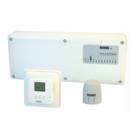
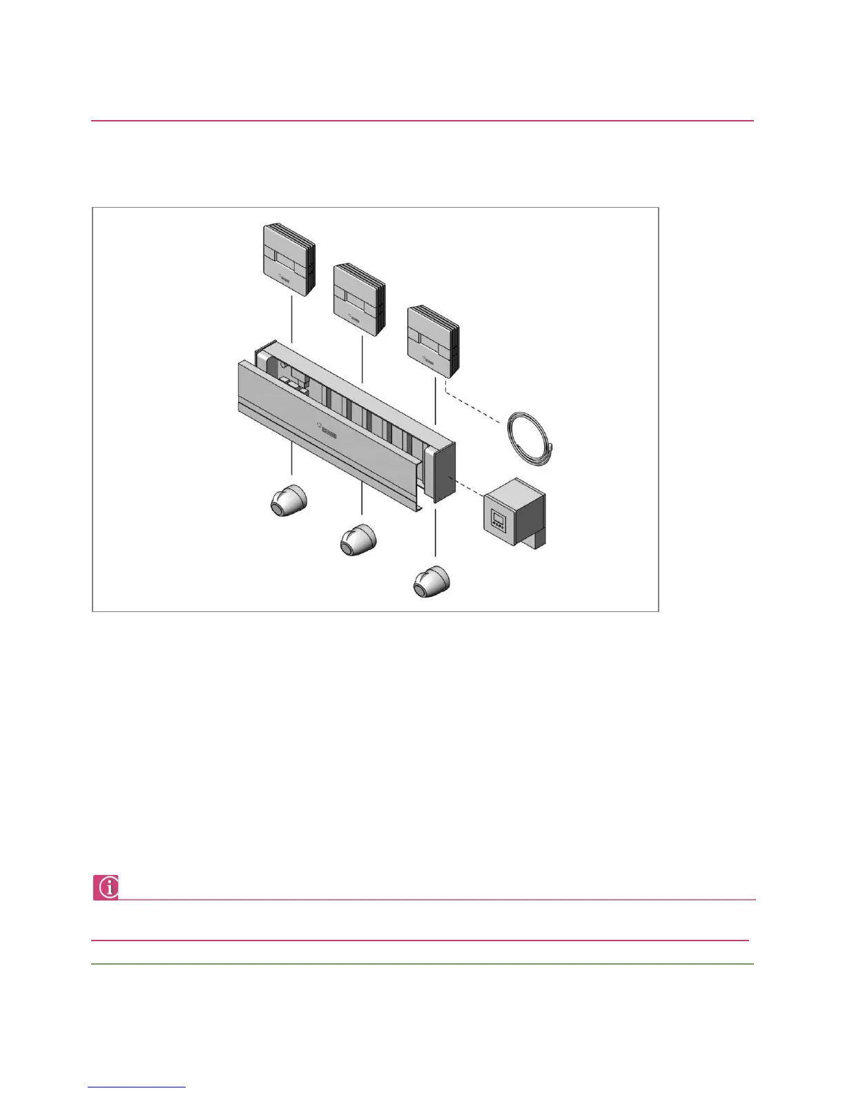
Fig. 3-1 System structure NEA control system
1 – NEA room controller
2 - NEA Wiring centre
3 - Actuators
4 - Timer
5 – Remote temperature probe
The NEA room controller, the thermal actuators and the optional timer are connected to the NEA wiring centre.
The NEA wiring centre offers a safe and clear wiring of the system in the manifold cabinet.
The wiring centre allows up to 6 room temperature controllers and a maximum number of 12 actuators to be connected.
For the central control of the setback times the NEA timer can be used as an option.
A remote temperature probe can be connected to the NEA HCT room controllers.
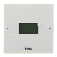
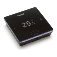
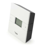
Only wiring centres NEA HC and room temperature controllers NEA HCT may be used in heating/cooling applications!
A mixed use of room temperature controllers NEA HCT together with room temperature controllers NEA H or HT is not possible!
 Loading...