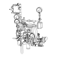
Inspection and Testing
1. Water supply — Conrm that valves controlling water supply
to the EX Valve are opened fully and properly monitored.
2. Alarm line — Conrm that the alarm line valve is open and
remains in this position.
3. Other trim valves — Conrm that the pushrod chamber
supply valve is open, as well as all pressure gauge valves.
The main drain valve, condensate drain valve, and alarm test
valve should be closed.
4. Ball drip valve — Push in on the plunger to be sure ball check
is off its seat. If no water appears, the Model EX Valve water
seat is tight. Inspect the bleed hole on the underside of the
pushrod chamber for leakage.
5. Supervisory pneumatic pressure — Inspect actuation piping
and system air (or nitrogen) pressure for conformance to
Table A.
6. Releasing device — Check outlet of the releasing devices
(i.e., hydraulic manual emergency station and solenoids)
for leakage. Also verify that tubing drain lines from releasing
devices are not pinched or crushed which could prevent
proper releasing of the EX Valve.
7. Testing alarms — Open the alarm test valve permitting water
from the supply to flow to the electric sprinkler alarm switch
and to the mechanical sprinkler alarm (water motor). After
testing, close this valve securely. Push in on the plunger of
ball drip valve until all water has drained from the alarm line.
8. Operational test — Open the Model B Manual Emergency
Station. Alternatively, deplete pneumatic pressure from
the sprinkler system. Note: AN OPERATIONAL TEST WILL
CAUSE THE MODEL EX VALVE TO OPEN AND FLOW
WATER INTO THE SPRINKLER SYSTEM.
9. Secure the Model B Manual Emergency Station in the OFF
position with nylon tie after EX Valve is reset.
Testing Detection System Without Operating
Model EX Valve
1. Close the valve controlling water supply to the system valve
and open the main drain valve.
2. Verify that valve supplying hydraulic pressure to the piston/
pushrod chamber is open, allowing water to enter the pushrod
chamber.
3. Deplete pneumatic pressure from the sprinkler system.
4. Loss of pneumatic pressure must result in a sudden drop of
water pressure in the pushrod chamber, as indicated by the
pressure gauge on the hydraulic release trim.
5. Reset the valve per the reset instructions.
Maintenance
The owner is responsible for maintaining the re protection system
in proper operating condition. Any system maintenance or testing
that involves placing a control valve or detection/control system out
of service may eliminate the re protection that is provided by the re
protection system.
The Reliable Model EX valve and associated equipment shall
periodically be given a thorough inspection and test. NFPA 25,
“Inspection, Testing, and Maintenance of Water Based Fire Protection
Systems,” provides minimum maintenance requirements. System
components shall be tested, operated, cleaned, and inspected
7.
Bulletin 739
January 2021
Page 7 of 9
www.reliablesprinkler.com
at least annually, and parts replaced as required. Replace any
components found to be corroded, damaged, worn, or non-operable.
Increase the frequency of inspections when the valve is exposed
to corrosive conditions or chemicals that could impact materials or
operation of the assembly.
If face plate is removed during maintenance, torque face plate bolts
to the following values during re-installation:
• 35 ft-lbs. (47 N-m) for 2” through 4” valves
• 70 ft-lbs. (95 N-m) for 6”-8” valves
Draining Excess/Condensate Water from the System
1. Notify the owner and monitoring company that maintenance is
being performed on the system.
2. Close the main water control valve.
3. Open the Main Drain Valve.
4. Open the Condensate Drain Valve until all water has drained.
5. Close Condensate Drain Valve.
6. Partially open the Main Water Control Valve.
7. Slowly close the Main Drain Valve.
8. Fully open the Main Water Control Valve.
9. Notify the owner and monitoring company that the system has
been returned to service.
Clapper Gasket and Seat Replacement Procedure
1. Disable detection system and supervisory pneumatic supply
to system.
2. Shut down the valve controlling the water supply to the system
and open the main drain valve. Open the condensate drain
valve. Close the pushrod chamber supply valve and open the
Model B Manual Emergency Station.
3. Remove the EX Valve front (handhold) cover and inspect the
seat, clapper, and seal assembly for damage. If inspection
indicates damage to the seal assembly only, replace as
follows:
4. Remove the bumpstop nuts and remove the seal assembly
. Install a new seal assembly and thread the bumpstop nuts
onto the threaded studs of the seal assembly. Tighten nger
tight plus ¼ to ½ turn.
5. If inspection indicates damage to the clapper, proceed to step
6.
6. At the rear of the valve, disconnect the condensate drain
trim section starting with the elbow connector. Then remove
the ¼” globe valve, followed by the ¾”x¼” reducing bushing.
Remove the retaining rings from the clapper hinge pin, push
the hinge through the condensate drain opening and remove
the clapper subassembly. Install a new clapper subassembly
in the reverse order making sure the clapper spacers are in
their proper position.
7. If the seat is damage, or it is suspected that the leakage is
through the seat O-rings, proceed to step 8.
8. Using Reliable P/N 6881603000 Seat Wrench for 2” (50mm),
2½” (65mm), 76mm and 3” (80mm) valve sizes, Reliable
P/N 6881604000 for 4” (100mm) valve size, Reliable P/N
6881606000 for the 6” (150mm) and 165mm valve sizes or
Reliable P/N 6881608000 Seat Wrench for 8” (200mm) valve
size, remove the seat by unscrewing. This will loosen the seat-
clapper-mounting ring subassembly.

 Loading...