8.
Bulletin 739
January 2021
Page 8 of 9
www.reliablesprinkler.com
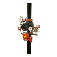
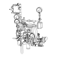
Solenoid Valve
WARNING: The owner is responsible for maintaining the
re protection system in proper operating condition. Any
system maintenance or testing that involves placing a control
valve or detection system out of service may eliminate the
re protection of that system. Prior to proceeding, notify
all authorities having jurisdiction. Consideration should be
given to employment of a re patrol in the affected area.
WARNING: Prior to operating the solenoid valve, be sure to close the
system control valve to avoid unintentional operation of the system.
1. Inspections: It is imperative that the system be inspected
and tested in accordance with NFPA 25 on a regular
basis. The frequency of the inspections may vary due to
contaminated water supplies, corrosive water supplies,
or corrosive atmospheres. In addition, the alarm devices,
detection systems, or other connected trim may require a
more frequent schedule. Refer to the system description
and applicable codes for minimum requirements.
2. The valve must be inspected at least monthly for cracks,
corrosion, leakage, etc., cleaned and replaced as necessary.
3. If leakage is suspected through the solenoid
valve, it should be replaced.
Troubleshooting
1. Mechanical sprinkler alarm not operating: This is most
likely caused by a clogged screen in the strainer of the water
motor. Proceed as follows: Remove plug from the strainer.
Remove and clean the screen. Replace the screen and
the plug, and then tighten securely (Ref. Bulletin 613).
2. Water leaking from Ball Drip. This can be
caused by either a water column on top of
the clapper or a supply water leakage.
a. Leakage due to water column. This condition is
caused by leakage past the clapper seal assembly. Be
sure the clapper seal and seat are free of any type of
debris or damage. If necessary, follow steps below to
replace the seal assembly and/or seat.
b. Supply water leakage. This condition is caused by
leakage past the lower seat O-ring. Follow steps below for
inspection and/or replacement of lower seat O-ring.
3. Air or nitrogen leaking from Ball Drip. This
condition is caused by leakage past either the
clapper seal assembly or the upper seat O-ring.
a. Clapper seal leak. Be sure the clapper seal and seat
are free of any type of debris or damage. If necessary,
follow steps below to replace the seal assembly and/or
seat.
b. Upper seat O-ring. Follow steps below for inspection
and/or replacement of upper seat
O-ring.
Clapper Gasket and Seat Replacement Procedure (cont.)
8 (cont). Reach into the valve and grasp the seat and remove
it from the valve. Then remove the clapper-mounting ring
subassembly from the valve. Visually examine all components
of the seat-clapper-mounting ring subassembly replacing
any component that appears damaged. New O-rings should
always be used for reassembly.
9. Reassembly: clean the bore of the valve body. Lubricate the
bore with O-ring grease. Lubricate and install the O-rings onto
the seat. Lubricate and install the mounting ring O-ring into the
body (8” (200mm) valve size only). Insert the clapper-mounting
ring subassembly into the handhold opening of the EX Valve
using caution to not damage or dislodge the mounting ring
O-ring (8” (200mm) valve size only). Align the mounting ring
so that the Lever is near the pushrod and the mounting ring
“ears” are between the tabs of the valve body. Insert the seat
into the valve body and through the clapper-mounting ring
subassembly. Start to tread the seat into the body by hand,
then tighten the seat with the seat wrench until it bottoms out
on the mounting ring. Verify that the seat-clapper-mounting
ring subassembly is in the fully down position between the
tabs of the body, and check to see that the lever lines up with
the pushrod. Reassemble the handhold cover and set up the
Model EX Valve as per the section “Resetting Model EX Valve
Single Interlock Preaction Systems”.
Pushrod Chamber Diaphragm and O-Ring Replacement
Procedure
A small bleed hole is located on the underside of the pushrod
chamber. If there is air or water leakage coming out of the bleed
hole:
a. Disable detection system and supervisory pneumatic supply
to system.
b. Shut down the valve controlling water supply to the system.
Relieve the inlet pressure by opening the main drain valve.
Close the valve that supplies water to the pushrod chamber,
and open the Model B Manual Emergency Station.
c. Remove the trim at the unions nearest to the pushrod chamber
cover.
d. Take the pushrod chamber cover off by removing the six
retaining screws.
CONDITION ONE (Water coming out of the bleed
hole):
Water coming out of the bleed hole is caused by a leaking
diaphragm. Visually inspect the pushrod chamber cover and
piston to determine what could have damaged the diaphragm and
then correct. Install a new diaphragm. NOTE: The diaphragm has
two different surfaces; it is not bi-directional. It will fail if installed
backwards! Roll the diaphragm so that the smooth surface (the
pressure side) conforms to the inside of the pushrod chamber
cover and the fabric side engages the pushrod, and reassemble
the six retaining screws with an installation torque of 15 foot-pounds
in a star pattern. Set up the Model EX Valve as per the section
“Resetting Model EX Valve Single Interlock Preaction Systems”.
 Loading...