
O
ofieldsSep 8, 2025
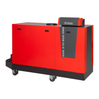
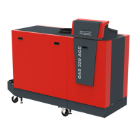
What to do if my REMEHA Gas 320 Ace Boiler has a 5x Flame Loss Error?
- AambermitchellSep 8, 2025
If flame loss occurs 5 times, try the following: Vent the gas supply to remove air. Check that the gas valve is fully opened. Check the gas supply pressure. Check the operation and setting of the gas valve unit. Make sure that the air supply inlet and flue gas outlet are not blocked and that there is no recirculation of flue gases.