EasyManua.ls Logo

Remote Control RCEL 005 - User Manual

Remote Control RCEL 005
2 pages
Print Icon
To Next Page IconTo Next Page
Loading...
- 1 -
Top Quality Valve Actuators
Electric Actuators
RCEL 005 / 005L
Installation
1. Mounting on valve A).
2. Electric wiring (B).
3. Adjusting (C).
4. Manual operation (D).
NOTE: Only electric wiring, according to
instruction B, is required when the actuator
is delivered from Remote Control mounted
on a valve. It is adjusted and ready for
operation.
1. Operate the valve manually to fully open
or fully closed position before the actuator
is mounted.
2. Operate the actuator manually (see D) to
fully open or fully closed position.
3. Check that the actuator and valve stem
are in correct position. Please note, valve
and actuator must be in the same mode
(fully open / fully closed) prior to the
assembly.
4. Mount the actuator on the valve and
check that the actuator and valve stems
are centered and aligned. If a mounting
bracket is used, the fi t must be checked
so that no distortion or play exists.
5. Operate the valve manually with the aid of
allen key (see D) and check that the valve
moves with normal resistance.
6. Check that all screws are correctly
tightened.
1. Loosen the screws on the cover and lift it off.
2. Check the voltage marked on the actuator
label.
3. Connect according to the enclosed wiring
diagram or, if the actuator is of standard
design, according to the wiring diagram
below. The wiring diagram is drawn in
unaffected position (the valve in intermediate
position).
4. Tes t run the actuator from the intermediate
position checking that the actuator turns in
the correct direction.
5. Tes t run the actuator and check that the limit
switches work correctly.
6. Check that the cable entries and possible
blind plug are sealed.
7. Mount the cover.
Wiring diagram No. ST 12000 A. Standard.
NOTE: Electric wiring must be carried out by
qualifi ed personnel only!
A. Mounting on Valve
B. Electric Wiring
WARNING!
Remove power before the cover
is dismantled! The actuator must be handled
with the utmost care when the cover is
removed and the power is connected.
Instruction
Question and Answer IconNeed help?

Do you have a question about the Remote Control RCEL 005 and is the answer not in the manual?

Summary

Installation

A. Mounting on Valve

Instructions for mounting the actuator onto the valve, ensuring proper alignment and fit before operation.

B. Electric Wiring

Guidelines for connecting the actuator's electric wiring, emphasizing safety and correct connections by qualified personnel.

C. Adjusting

a. Adjustment of cams for limit switches

Detailed steps to adjust the cams for closed (CLS) and open (OLS) limit switches on the electronic card.

D. Manual Operation

Overview

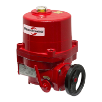
The Remote Control RCEL 005 / 005L Electric Actuator is a robust and reliable device designed for controlling valves. This actuator is engineered for precision and ease of use, ensuring optimal performance in various industrial applications. It is delivered pre-mounted on a valve and pre-adjusted, making it ready for immediate operation upon installation.

Function Description

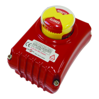
The RCEL 005 / 005L Electric Actuator's primary function is to automate the opening and closing of valves. It operates by converting electrical energy into mechanical motion, which then manipulates the valve stem to achieve the desired position (fully open, fully closed, or intermediate). The actuator is equipped with limit switches that precisely control the extent of valve travel, ensuring that the valve stops at the correct open and closed positions. Auxiliary limit switches are also included, providing additional control and feedback capabilities for more complex systems. A thermal protector is integrated to safeguard the motor from overheating, enhancing the actuator's longevity and reliability. The device also features an LED lamp to indicate its open/close status, offering clear visual feedback on its operational state.

Usage Features

The RCEL 005 / 005L Electric Actuator is designed for straightforward installation and operation.

Installation:

  1. Mounting on Valve: Before mounting the actuator, the valve should be manually operated to its fully open or fully closed position. Similarly, the actuator itself should be manually operated to its fully open or fully closed position. It is crucial that both the valve and the actuator are in the same mode (e.g., both fully open or both fully closed) prior to assembly to ensure proper alignment. The actuator is then mounted onto the valve, ensuring that the actuator and valve stems are centered and aligned. If a mounting bracket is used, its fit must be checked to prevent distortion or play. After mounting, the valve should be manually operated using an Allen key to confirm that it moves with normal resistance. All screws must be correctly tightened to secure the assembly.
  2. Electric Wiring: Electrical wiring must be performed exclusively by qualified personnel. The process involves loosening the cover screws and lifting the cover. The voltage marked on the actuator label should be verified. Connections are made according to the provided wiring diagram, which illustrates the actuator in an unaffected (intermediate) position. After wiring, a test run is conducted from the intermediate position to ensure the actuator turns in the correct direction. Further test runs confirm the correct functioning of the limit switches. Finally, all cable entries and any blind plugs must be sealed, and the cover re-mounted.
  3. Adjusting: The actuator comes pre-adjusted when delivered mounted on a valve. However, if adjustments are needed, the final cam adjustments for the limit switches can be made. This involves operating the actuator from one end position to the other multiple times. The indicator disc is adjusted to visually correspond with the valve position. A test run confirms that the limit indicators are working correctly. The cover is then mounted.
    • Adjustment of Cams for Limit Switches: To adjust the cams, the actuator is first manually operated to the closed position. The lower cam, marked CLS on the electronic card, is then adjusted for the closed position. Next, the actuator is manually operated to the open position, and the upper cam, marked OLS on the electronic card, is adjusted for the open position. A final test run verifies the adjustments.
  4. Manual Operation: For manual operation, a 6mm Allen key, conveniently mounted underside the actuator, is used. The Allen key is inserted, and the valve is turned to the desired position. Turning clockwise closes the valve, while turning anti-clockwise opens it. After manual operation, the Allen key should be returned to its holder.

Maintenance Features

The RCEL 005 / 005L Electric Actuator is designed with maintenance considerations in mind, emphasizing safety and ease of access for necessary procedures.

  1. Safety First: A critical warning highlights the importance of removing power before dismantling the cover. This ensures the safety of personnel performing maintenance or adjustments. The actuator must be handled with the utmost care when the cover is removed and power is connected, underscoring the potential hazards of live electrical components.
  2. Accessible Components: The design allows for easy access to internal components by simply loosening the screws on the cover. This facilitates checks, adjustments, and troubleshooting.
  3. Sealed Enclosure: The requirement to seal cable entries and any blind plugs after wiring or maintenance is crucial for maintaining the integrity of the actuator's enclosure. This protects internal components from environmental factors such as moisture and dust, which can degrade performance and shorten the device's lifespan.
  4. Visual Indicators: The LED lamp for open/close status provides immediate visual feedback on the actuator's operational state, aiding in quick diagnostics and verification during maintenance checks.
  5. Robust Construction: The overall robust construction and quality materials used in the RCEL 005 / 005L contribute to its durability and reduce the frequency of maintenance. The thermal protector further enhances reliability by preventing motor damage due to overheating.

The Remote Control RCEL 005 / 005L Electric Actuator is a comprehensive solution for automated valve control, combining precise functionality with user-friendly installation, operation, and maintenance protocols.

Remote Control RCEL 005 Specifications

General IconGeneral
ModelRCEL 005
CategoryController
Operating RangeUp to 10 meters
MaterialPlastic
ConnectivityInfrared (IR)

Related product manuals