Do you have a question about the Remote Control RCEL060 and is the answer not in the manual?
Warning about avoiding personal injury and property damage by turning off power before removing covers.
Specifies that explosion-proof products must be used in appropriate environments and temperatures.
Details the flameproof enclosure level (Ex d IIB T4) and operating temperature range.
Specifies enclosure type (IP67, Nema 4/6, Ex d IIB T4) and ambient temperature range.
Details main power requirements and specifications for limit and torque switches.
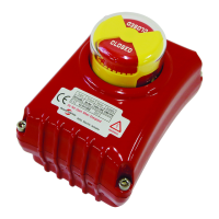
Describes control unit features, position indicator, and LED lamp functions.
Covers conduit entry types and potentiometer specifications.
Information on actuator mounting flanges manufactured to ISO5211 standards.
Instructions for separating and machining the drive bushing to fit the valve stem.
Specifies maximum bore sizes for drive bushings based on actuator model.
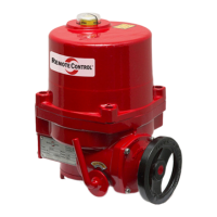
Step-by-step guide for operating the actuator manually using the hand wheel.
Instructions for setting the open and closed limit switches.
Caution against tampering with factory-set over torque switches.
Procedure for setting mechanical limit stops to prevent over-travel damage.
Explanation of the local control unit's lamps and LCD display.
Describes button operations for control and settings.
Details how to enter the actuator's setting mode.
Explains button presses for navigating the setup menu.
Lists key configurable parameters like TQ CHECK, CYCLE, PIU CHECK, AUTO SCAN, DEAD BAND, TIME DELAY, FAULT DIR, ESD DIR.
Configuration options for HOLD and INCHING modes.
Settings for CLOSE, OPEN, and STOP modes.
Configuration for TQ OFF and TQ ON settings.
Settings for Actuator Position, Potentiometer, and AUTO SCAN.
Specific settings for Dead Band, e.g., 2.5% and 1.5%.
Configuration for Time Delay, e.g., 1.5 sec and 0.5 sec.
Configuration options for FAIL CLOSE, FAIL OPEN, and FAIL STOP.
Diagnosis and solutions for MOTOR TP, PH REV, and PH LOSS faults.
Diagnosis for OPEN/CLOSE TORQUE and OVER/UNDER LIMIT faults.
Diagnosis and solutions for POT LOSS and POT REV faults.
Details BAUD RATE and cable length specifications for Profibus.
Defines the 1-byte control order structure from Master to Slave.
Explains the bit-level format for control commands and data.
Specifies position data (0-255) for actuator operation.
Details the first byte of response data representing actuator position.
Details the second byte of response data for actuator status.
Details the third byte of response data for actuator and fault information.
Overview of the SST Profibus Configuration tool interface.
Steps for selecting the master and assigning station addresses.
Finalizing master settings within the configuration tool.
Procedure for adding slave actuator GSD files to the configuration.
Setting up address, input, and output modules for slaves.
Configuring attendance and achieving on-line operation status.
Description of output view, input view, and actuator address modes.
Details of the control board layout and LED indicator functions.
Diagrams and notes for limit switch contact configurations.
Wiring diagram for the main board, including power and signal terminals.
Schematic showing customer wiring connections for inputs and outputs.
Overview of control board components and LED status indicators.
Details on limit, monitor, and fault contact positions and wiring.
Wiring diagram for main board components, power, and signals.
Explanation of customer wiring for input and output lines.
| Brand | Remote Control |
|---|---|
| Model | RCEL060 |
| Category | Controller |
| Language | English |