EasyManua.ls Logo

Remote Control RCEL Series - User Manual

Remote Control RCEL Series
16 pages
To Next Page IconTo Next Page
Loading...
Top Quality Valve Actuators
Made in Sweden
Instruction
Pro-Bus with LCU
RCEL
- 1 -
www.rotork.com www.remotecontrol.se
Standard Specication
Enclosure Weatherproof enclosure IP67
Nema 4 and 6
Ex d IIB T4
Ambient
temperature
-20 ºC to +55 ºC
Main Power 1PH AC110 / 220V, 50 / 60 Hz
Limit Switches Open / Close Limit Switch
(Max 250VAC 15A)
Torque Switches Open / Close Torque Switch
(Max 250VAC 15A)
Control Unit 1. Non Intrusive Push Buttons
(Open / Stop / Close)
2. Non Intrusive Selector Switch
(Remote / OFF / Local)
Position Indicator Digital Display (0~100%)
LED Lamp Remote / Local / Fault
Open / Close
Remote Dry
Contact
(Max 250VAC 5A)
Full Open / Close
Fault Signal
Monitor (Remote / Local)
Conduit Entry PF 3/4” x 2
Option: M20 Pitch 1,5 x 2,
NPT 3/4” x 2
Potentiometer 0 ~ 1 kΩ
ELECTRICAL SHOCK HAZARD.To avoid serious personal
injury, property damage, turn off ALL power to the actuator
before removing the cover.
Before installation, verify the nameplate information informa-
tion to insure the correct model number and voltage of the
actuator.
Be sure to completly review the actuator manual prior to
operation.
Final limit switch adjustment MUST be done after mounting
the actuator to the valve. Incorrect adjustment may cause
actuator failure.
Over torque switches are factory set. Tampering with the over
torque switch settings may damage the actuator and void the
warrenty.
To minimize the possible damage caused by condensation,
be sure to energize the heater.
Care should be taken when wiring 3 phase actuators.
Conrm proper rotation and limit switch shut-off function
during the initial operation. If the actuator rotates in the
reverse direction, then the phasing needs to be corrected
by switching two of the 3 phase wires on the terminal block.
CAUTION
Explosion-proof products must be used under the
temperature and environment appropriate for the product
spec.
Explosion proof actuators and wiring must be properly sealed
prior to operation. Improper installation may cause
a hazardous condition and failure of the explosion proof
enclosure. The manufacture is not responsible for any losses
or damages caused by incorrect installation.
CAUTION
Flameproof Enclosure Level and Enviroment of Actuator
Ex d IIB T4 -20°C ~ +55°C
Question and Answer IconNeed help?

Do you have a question about the Remote Control RCEL Series and is the answer not in the manual?

Remote Control RCEL Series Specifications

General IconGeneral
BrandRemote Control
ModelRCEL Series
CategoryController
LanguageEnglish

Summary

General Safety and Installation

Electrical Shock Hazard

Warning to turn off power before cover removal to prevent injury.

Installation and Operation Guidelines

Verify nameplate, review manual, correct phasing, and manage condensation.

Limit Switch and Torque Settings

Proper adjustment of limit switches and non-tampering of torque switches.

Standard Specifications

Enclosure and Environment Ratings

Specifies enclosure, temperature, and flameproof ratings (IP67, Ex d IIB T4).

Power, Control, and Connectivity

Details main power, control unit features, and interface options.

Actuator Mounting Flange

ISO5211 Standards and Dimensions

Mounting flange manufactured to ISO5211 standards with detailed dimensions.

Mounting Kit Requirements

Need for a mounting kit if direct valve mounting is not possible.

Actuator Drive Bushing

Drive Bushing Separation and Adaption

Instructions for separating and machining the drive bushing for valve stem compatibility.

Drive Bushing Bore Size Specifications

Details maximum bore sizes for drive bushings for various RCEL models.

Manual Operation Procedures

Engaging and Performing Manual Operation

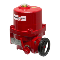
Steps to engage manual override and operate the actuator using the hand wheel.

Limit Switch Adjustment Process

Detailed steps for setting both closed and open limit switches correctly.

Over Torque Switch Setting

Factory Settings and Warnings

Over torque switches are factory set; tampering voids warranty.

Mechanical Limit Stop Setting

Purpose and Setting Procedure

Mechanical stops prevent over-travel; detailed setting steps provided.

Verification of Limit Stops

Check proper function after setting to ensure motor shut-off.

Local Control Unit Functions

Control Unit Components and Indicators

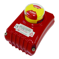
Overview of buttons, display, and LED lamps on the local control unit.

LCD Display Information

Explains how the LCD displays actuator mode, messages, and position status.

Push Button and Setting Mode Navigation

Push Button Operations

Defines functions of OPEN, STOP, CLOSE buttons in Local/Off modes.

Entering and Navigating Setup Menu

Steps to enter setting mode and navigate through menu options.

Setup Menu Options Overview

Lists available setup options like INCH/HOLD, ESD DIR, FAULT DIR.

Specific Setting Configurations

Setting Mode Entry and Flow

Reiteration of setting mode entry and visual guides for various settings.

HOLD, INCHING, and CLOSE Settings

Detailed sequences for configuring HOLD, INCHING, and CLOSE modes.

OPEN and STOP Setting Sequences

Visual flowcharts for setting OPEN and STOP modes.

Advanced Setting Parameters

Torque Check and Cycle Settings

Configuration for Torque Check (ON/OFF) and CYCLE count.

Potentiometer and Auto Scan Settings

Procedures for PIU CHECK (Potentiometer) and AUTO SCAN.

Dead Band Adjustment

Details on adjusting the Dead Band parameter for signal range.

Time Delay and Fail-Safe Configuration

Time Delay Settings

Setting the Time Delay for signal implementation.

Fail Direction Settings

Configuring actuator behavior for emergency shutdown (FAIL STOP, OPEN, CLOSE).

Self Diagnosis and Troubleshooting

Motor and Torque Faults

Troubleshooting for MOTOR TP, OPEN TORQUE, and CLOSE TORQUE faults.

Limit and Potentiometer Faults

Diagnosing and resolving UNDER/OVER LIMIT and POT LOSS/REV faults.

Profibus Communication Protocol

Profibus Highway and Addressing

Overview of RS485 communication, device connection, and address reservation.

Baud Rate and Cable Lengths

Table correlating baud rates with maximum permissible cable lengths.

Control Order Data Format

Structure of the 1-byte control order for Master-Slave communication.

Profibus Data Exchange Details

Position Data Representation

How actuator position is communicated via bits.

Actuator Status and Fault Data

Interpretation of status, act, and fault bits from the actuator.

Profibus Configuration Tool Usage

Configuration Tool Operation

Steps for using the SST Profibus Configuration tool.

Master Configuration Steps

Selecting master, setting address, and finishing master configuration.

Profibus Integration and Operation

Adding Slave GSD File

Process of incorporating the actuator's GSD file into the configuration.

Module Settings and On-line Status

Configuring modules and achieving on-line communication.

Data Exchange Monitoring

Observing input/output views in the data exchange mode.

Electrical Wiring and Connections

Control and Main Board Wiring

Details connections for limit switches, potentiometers, and remote signals.

Actuator, Power, and Customer Wiring

Shows actuator power, earth grounding, and customer wiring interfaces.

Input and Output Line Connections

Wiring for various input and output signal lines.

Wiring Specifications and Company Info

Limit, Torque, and Monitor Contact Details

Specifications for limit, torque, and monitor contact positions.

Terminal Functionality

Explains the purpose of each terminal connection.

Company Contact Information

Contact details for Rotork Sweden AB.

Related product manuals