12 1
24 13
3457811 691012
24 23 21 20 19 18 17 16 15 14 1322
12V
GND
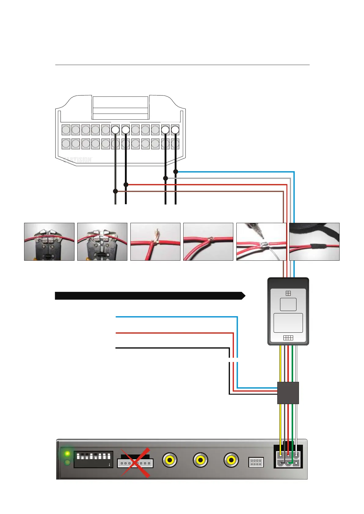
(7) Ground (BROWN)
Backside of the 24 Pins connector seen from behind the monitor
12345678
DIP ON
(6) 12V +30 (RED)
12
(2) CAN - (GREY)
(1) CAN + (BLUE)
YELLOW
RED
BLACK
GREEN
WHITE
12V BATT
12V ACC
GROUND
12V REVERSE
INTERFACE TRIGGER (5~12V PULSE)
1
2
3
4
5
6
7
8
RGB
VIDEO 1
VIDEO 2
X
CAMERA
X
X
X
UP (OFF)
ONLY WHEN VIDEO 1 WILL BE USED
ONLY WHEN ALSO VIDEO 2 WILL BE USED
X
ONLY WHEN THE REVERSE CAMERA WILL BE USED
X
X
X
VIDEO 1 VIDEO 2 CAMERA
CAN BUS
~~ ~~
CAN+
CAN-
1. IDRV Swich
2. SPEED
3. LIGHT
4. REVERSE
5. ACC OUT
6. AIR CON
7. BATT
8. GND
OUT
1. BATT
2. GND
3. CAN-
4. CAN+
POWER SUPPLY
Add an additional cable without cutting the original cable
Position 7
Position 6
Position 2
Postion 1
Ground
12V BATT
CAN low
CAN high
Add the BROWN ground cable from the CAN box
Add the RED 12V BATT cable from the CAN box
Add the GREY CAN- cable from the CAN box
Add the BLUE CAN+ cable from the CAN box
Position 7
BLUE
ORANGE
BLACK
12V TRIGGER (ONLY when CAN box doesn’t create a reverse signal)
12V Camera power
Camera GROUND
See the additional explanation about the camera connection of the wires on the last page!