MAPPING OUT THE MIRROR BACK
PLATE INSTALLATION AREA CONT’D
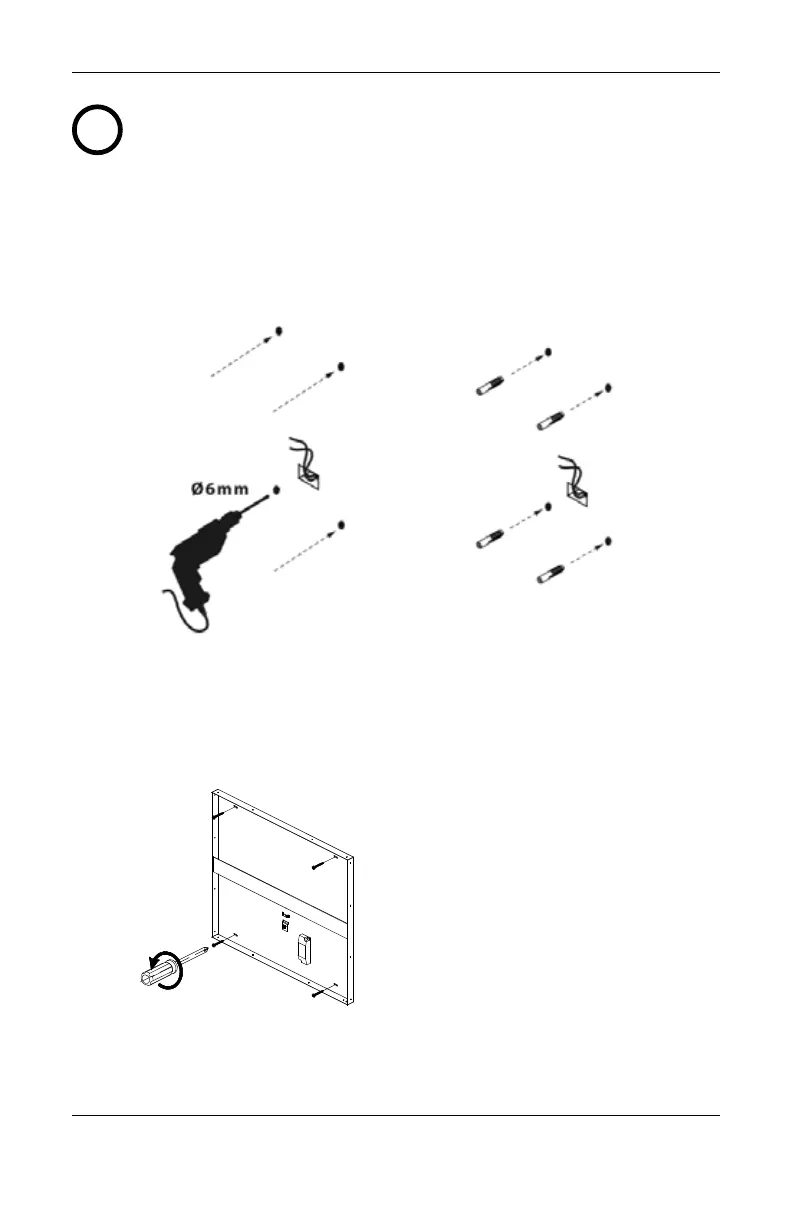
1
C. Using a 1/4" drill bit. Drill holes in the corresponding marks
from Step A (Fig.3). Place supplied anchors in the holes (Fig.4).
Secure back plate with screws supplied to anchors (Fig.5).
Fig.3 Fig.4
Fig.5
Drill holes
Add anchors*
*Note: If back plate is secured to studs,
anchors are not required
Secure back plate to anchors
4 | ENGLISH | HARDWIRED LED ILLUMINATED MIRROR | INSTRUCTION MANUAL
PART# 98-3200 REV.B
ENGLISH