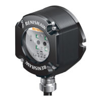
The OMI-2H is a combined optical receiver and machine interface designed for mounting within a machine's working envelope. It operates using a 'Modulated' optical transmission mode and is compatible with machine probes that also operate in 'Modulated' mode. The primary function of the OMI-2H is to convert signals from an optical probe into a voltage-free solid-state relay (SSR) output for transmission to the CNC machine controller.
Important Technical Specifications
Principal application: The OMI-2H processes signals from RENISHAW™ or standard probes and converts them into machine outputs, which are then transmitted to the CNC control. The system allows two probes to be used with one interface.
Transmission type: Infrared optical transmission (modulated).
Probes per system: Two.
Compatible probes: OMP40-2, OMP40M, OLP40, OMP60, OMP60M, OMP400, OMP600, and OTS.
Operating range: Up to 6 m (19.7 ft).
Weight: OMI-2H including 8 m (26.2 ft) of cable = 720 g (25.40 oz).
Supply voltage: 12 Vdc to 30 Vdc. The input voltage ripple must not cause the voltage to fall below 12 V or rise above 30 V.
Supply current:
- Transmitting: 160 mA peak.
- Receiving: 40 mA average.
- Note: @24 Vdc, all outputs open circuit.
M-code inputs: Level 10 V to 30 V (10 mA @ 24 V).
Output signal: Probe status (Voltage-free solid-state relay (SSR) output).
Switching time (with 10 mA load):
- Open to closed: 100 µs max.
- Closed to open: 25 µs max.
Input/output protection: Supply protected by resettable fuse. Outputs protected by overcurrent protection circuit.
Cable (to machine control):
- Specification: Ø5.8 mm (0.23 in), 6-core screened cable, each core 18 x 0.1 mm.
- Length: 8 m (26 ft). Maximum length of the specified cable must not exceed 25 m (82 ft).
Diagnostic LEDs: Start, low battery, probe status, error, active system, and signal condition.
Mounting: Flush mounting or directional mounting with optional mounting bracket (available separately).
Environment:
- IP rating: IPX8, BS EN 60529:1992+A2:2013.
- IK rating: IK03, BS EN 62262:2002+A1:2021 [for glass window].
- Storage temperature: –25 °C to +70 °C (–13 °F to +158 °F).
- Operating temperature: +5 °C to +55 °C (+41 °F to +131 °F).
Usage Features
Visual Diagnostics: The OMI-2H provides a visual indication of system status through various LEDs:
- START SIGNAL LED (yellow): Flashes once when a machine control START signal is commanded.
- LOW BATTERY LED (red): Lit when the activated probe battery voltage falls below a set level. The probe battery should be replaced as soon as practicable.
- PROBE STATUS LED (green, red): This bicolour LED is lit when the OMI-2H is powered. Green indicates the probe is seated, while red indicates the probe is triggered or an error has occurred. The colour change coincides with the probe status output devices changing state.
- ERROR LED (red, blue, yellow): Indicates a transmission error condition, such as an obstructed optical beam, probe out of optical range, probe switched off, or a dead battery.
- Red: No transmission (signal from probe failed or stopped).
- Blue: Multiple probes detected (a second modulated signal is being received).
- Yellow: Interference (interference or a weak probe signal is being received).
- Note: A blue or yellow error condition resulting from the loss of a good probe signal will persist until the active system input (Probe 1 or Probe 2) is deactivated.
- SIGNAL CONDITION LED (red, yellow, green): This tricolour LED is lit when the OMI-2H is powered:
- Red: No communication (no signal from the probe).
- Yellow: Interference (signal received from the probe is too weak, or interference is present).
- Green: Good communication (signal received from the probe is good).
- ACTIVE SYSTEM LEDs (green): Lit green to show which system input (Probe 1 or Probe 2) is active. It remains active as long as the relevant probe is in range and operational. Off when system input is inactive.
Machine Start Inputs: The OMI-2H uses level machine inputs to define the active probe. When the respective input is active, the probe is switched on. If both inputs are active, the system will default to an error.
Probe Status Output (SSR): The probe status output indicates the status of the selected probe (only one probe can be selected at a time). An output overload will cause the Low Battery, Probe Status, and Error LEDs to flash red, and the probe status output will be triggered (SSR open). To reset, turn off the power supply and remove the source of the problem.
Switch SW2: This internal switch allows configuration of the START RANGE and Rx RANGE. Access to the switch requires removing the window.
- START RANGE: 50% or 100%.
- Rx RANGE: 50% or 100%.
Switch On / Switch Off Method: The OMI-2H operates using only optical on/optical off as the switch on/switch off method. Optical on/optical off is available with all Renishaw's OMP range of spindle probes and the optical tool setter (OTS). Time out, spin on/spin off, and shank on/shank off options are not compatible with the OMI-2H.
Start Up Times:
- Normal operation: 410 ms max. for modulated probes; 1 sec max. for strain gauge probes.
- Turn off time: 0 seconds.
- Normal operation refers to when the on/off status of the probes is in synchronisation with the receiver on/off status. The active probe should correspond to the respective active system LED.
- When changing from Probe 1 to Probe 2, or Probe 2 to Probe 1, allow 1 second between the cancelling of one machine start input and raising of the other start input, also allow 1 second when turning the probe off and back on again.
Synchronisation Recovery: Under abnormal operating situations, the system may lose synchronisation between the receiver and probes. An internal synchronisation recovery will be initiated when the next machine input is received. The maximum time for system recovery from an abnormal operating situation is 3.5 seconds. Such a time delay could cause a machine alarm if controllers require ready signals within a time of less than 3.5 seconds. When used in conjunction with an OMP400 or OMP600, ensure the probe is set to the standard switch-on delay.
Maintenance Features
General Maintenance: You may undertake the maintenance routines described in these instructions. Further dismantling and repair of Renishaw equipment is a highly specialised operation, which must be carried out at authorised Renishaw Service Centres. Equipment requiring repair, overhaul, or attention under warranty should be returned to your supplier.
Cleaning the Interface: Wipe the window of the interface with a clean cloth to remove machining residue. This should be done on a regular basis to maintain optimum transmission.
Removing the OMI-2H Window: It is not necessary to remove the OMI-2H from the machine when adjusting the switch or installing replacement parts. The window may be removed and replaced to change the switch settings.
- Clean the OMI-2H to ensure no debris enters the unit.
- Remove the four cover screws using a 2.5 mm A/F hexagon key. Two screws are short and two are long. Two of the cover holes are threaded (A), and two are plain (B).
- The window fits tightly on the OMI-2H body and is removed using the two long screws, which are inserted into the threaded holes (A). Tighten each screw a few turns at a time to pull the window up evenly. When it is clear of the body, remove the window and screws completely.
- Caution: Do not remove the window by twisting or rotating.
Fitting the OMI-2H Window:
- Before fitting the window, check for any damage to screws or scratch marks which could prevent sealing.
- Ensure the O-ring seating in the OMI-2H body is clean.
- Ensure the O-ring and window are clean.
- Insert the two short screws into window holes (A) and tighten to 0.3 to 0.5 Nm (0.22 to 0.37 lbf.ft).
- Place the window complete with the O-ring onto the OMI-2H body. The O-ring should be lightly lubricated with grease.
- Insert the long screws into holes (B) and tighten each screw a few turns at a time to pull the window down evenly. There may be some resistance due to compression of air trapped inside the body. Tighten to 0.9 to 1.1 Nm (0.66 to 0.81 lbf.ft).
Cable Sealing: Coolant and dirt are prevented from entering the OMI-2H by the cable sealing gland. The OMI-2H cable can be protected against physical damage by fitting a flexible conduit if required. A recommended flexible conduit is Anamet™ Sealtite HFX (5/16 in) polyurethane. A conduit kit is available (Part No. A-4113-0306).
- Cautions: Failure to adequately protect the cable can result in system failure due to either cable damage or coolant ingress through cores into the OMI-2H. Failure due to inadequate cable protection will invalidate the warranty. When tightening or loosening nut B on the conduit, ensure that torque is only applied between A and B.
Screw Torque Values:
- Mounting bracket screws (3.0 mm A/F): 2 Nm (1.47 lbf.ft).
- OMI-2H mounting screws (8.0 mm A/F): 5 Nm (3.68 lbf.ft).
- Conduit gland nut (22.0 mm (7/8 in) A/F): 22 Nm (16.22 lbf.ft) MAXIMUM.