06
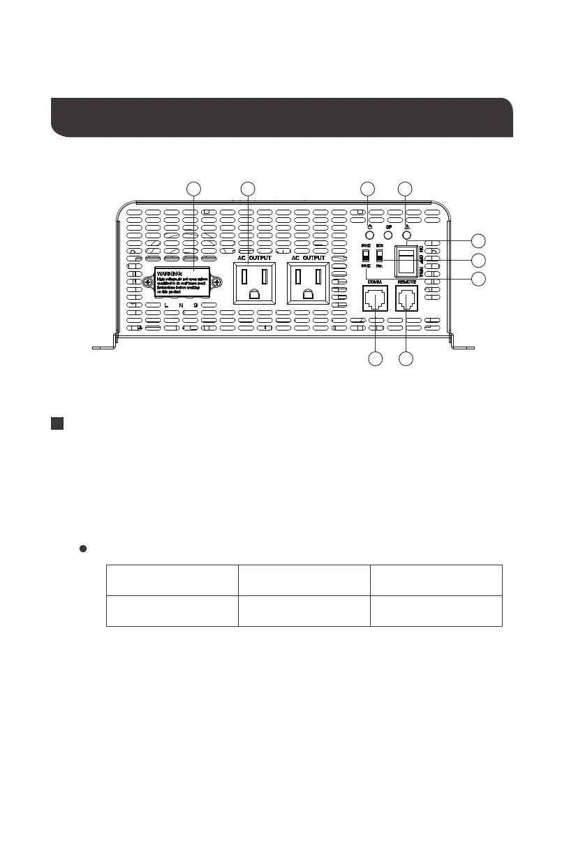
Identification of Parts (AC Side)
Key Parts
1.
High Output AC Terminals
— These terminals are for connecting 110 Volt AC devices
that require more than 15 amps to operate or for connection to distributed wiring that
has multiple AC outlets. Remove the two screws on protective cover to access the
terminals. Any AC output wiring that is directly connected must comply with US National
Electric Code (NEC) wiring gauge recommendations.
NEUTRAL and GROUND are bonded inside the inverter to comply with the National
Electric Code (NEC) requirement that any AC source must have aneutral to ground
connection.
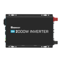
Figure 2: 2000W Inverter
LEFT
Neutral (N) Ground(G)
Middle Right
Live(L)
2. Power LED (Green)
— When this green LED is lit, the inverter is operating.
Facing the front panel, the terminals are:
67
4
9
8
251 3
 Loading...