EasyManua.ls Logo

Renogy 2000W - User Manual

Renogy 2000W
40 pages
Print Icon
To Next Page IconTo Next Page
Loading...
2000W/3000W
Version 1.1
Pure Sine Wave Inverter & Charger
PCL
SERIES

Other manuals for Renogy 2000W

Questions and Answers

  • J
    Jennifer GilbertAug 16, 2025
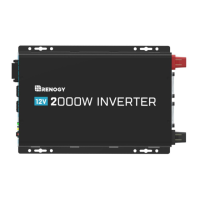
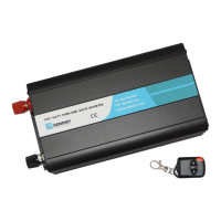
    Why is my Renogy 2000W Inverter indicator alarm beeping?
    • S
      Samuel LuceroAug 16, 2025
      If the indicator alarm on your Renogy inverter is beeping, it could be due to the following reasons: * The input voltage is below 10.5V. To resolve this, ensure the input voltage remains above 10.5V. * The input voltage is above 16.0V. To fix this, maintain the input voltage below 16.0V.
  • M
    Melissa MurrayAug 19, 2025
    What to do if Fault LED is lit, Renogy 2000W shut down and alarm is on?
    • T
      Timothy ShortAug 19, 2025
      If the Fault LED is lit, the Renogy inverter has shut down, and the alarm is on, there could be several reasons: * The input voltage is below 10V. To resolve this, ensure the input voltage remains above 10V. * The input voltage is above 16.5V. To fix this, maintain the input voltage below 16.5V. * The inverter is overheating. If this is the case, allow the inverter to cool down. * There is inadequate ventilation. Make sure there is adequate ventilation around the inverter. * The load on the inverter is too high. Reduce the load on the inverter. * The operating equipment draws too much power. Either use a higher wattage inverter or a lower-powered device. * The inverter is short-circuited. Disconnect the inverter and turn off the ON/OFF switch to reset it.
  • I
    Isaiah BrownAug 21, 2025
    What to do if Yellow LED is lit and Renogy 2000W shut down?
    • S
      Suzanne JonesAug 22, 2025
      If the yellow LED is lit and the Renogy inverter has shut down, it is because the GFCI tripped. To resolve this, disconnect appliances and turn off the ON/OFF switch to reset.
  • R
    Rebecca AllenAug 25, 2025
    What to do if Renogy 2000W Inverter does not power on?
    • A
      Amy ColemanAug 26, 2025
      If your Renogy Inverter doesn't power on even with the battery cables connected, the inverter needs a minimum of 11 volts to operate. Use a multimeter to ensure the battery levels are suitable. If the voltage is adequate, inspect the wire connections for any breaks or tears.
  • J
    James MillerAug 27, 2025
    What to do if my Renogy Inverter shows Over Load protection?
    • T
      Tracy HollandAug 27, 2025
      If your Renogy Inverter is showing an overload protection error, turn it off immediately. Check the power requirements of your electronic devices and make sure the total wattage (volts x amps) doesn't exceed the inverter's specifications. Power strips can be a common cause of overloads. Some devices need a high surge of power to start, so ensure all AC appliances are off before turning the inverter on.
  • B
    Benjamin DavisAug 30, 2025
    Why does my Renogy Inverter AC shuts down after some use?
    • M
      mary25Aug 30, 2025
      If your Renogy Inverter's AC output shuts down after some use, it might be due to an overload caused by the electronic devices you are using. Many electronics have an initial power surge that can trigger the inverter's overload protection, causing it to shut down. Reduce the load on the inverter, check all connections and power specifications, and then reset the inverter by turning it off for about 20 seconds before powering it back on.
  • J
    Julie ChristianSep 2, 2025
    How to fix Under Voltage or Over Heat Protection on Renogy 2000W?
    • B
      Brian Perkins DVMSep 2, 2025
      To address under voltage or overheating issues with your Renogy Inverter, use a multimeter to check the battery voltage. Ensure it's within the inverter's rated specification (at least 11 ± 0.5 volts). If the voltage is too low, disconnect the battery if necessary. If the issue persists, relocate the inverter to a cooler area.
  • J
    Jonathan MurphySep 4, 2025
    What to do for Over Voltage Protection on Renogy Inverter?
    • T
      Tammy FordSep 5, 2025
      If your Renogy Inverter is experiencing over voltage protection issues, use a multimeter to check the battery voltage. Make sure the battery voltage is not exceeding the inverter's rated specification. The maximum input voltage should not exceed 16 ± 0.5 volts.
  • J
    James BraySep 7, 2025
    How to troubleshoot Short Circuit on Renogy 2000W Inverter?
    • J
      jamessharpSep 7, 2025
      If your Renogy Inverter is experiencing a short circuit, check the battery connections to the inverter to ensure continuity. If there's an in-line fuse, check if it has blown. Reset the inverter by turning it off for about 5 seconds and then powering it back on. A short might occur down the DC line connecting to the inverter.
  • L
    Lisa BentleySep 10, 2025
    Why does my Renogy Inverter cause radio interference?
    • M
      Matthew JohnsonSep 12, 2025
      If your radio or television is experiencing interference when using a Renogy Inverter, it's because inverters contain internal switching devices that can generate electromagnetic interference (EMI). To minimize this, ensure the inverter is properly grounded and located as far away from radios, televisions, and other audio/visual devices as possible.

Summary

General Information

Product Overview

Identification of Parts

Identifies the various components and connection points of the inverter unit.

Unit Dimensions

Provides the physical dimensions of the inverter unit.

Included Components

Lists and describes the components included with the inverter charger.

Battery Temperature Sensor (BTS)

Details the battery temperature sensor and its function in adjusting charging voltage.

Wired Remote Control Operation

Installation Guidelines

Location Recommendations

Recommends suitable locations for installing the inverter to ensure optimal performance and safety.

Sizing a Battery Bank

Guidance on determining the appropriate battery bank size for the inverter system.

Grounding

Explains the importance and methods of properly grounding the inverter for safety.

DC WIRING

Instructions for connecting the DC power source to the inverter.

AC WIRING

Instructions for connecting the AC power source and loads to the inverter.

Automatic Neutral-to-Ground Bond Switching

Explains the automatic neutral-to-ground bond switching feature for safety.

Automatic Transfer Relay

Details the automatic transfer relay switch that manages AC input power.

Auto Generator Start

Explains the auto generator start feature for automatic generator operation.

Operation and Controls

Function Keys

Describes the function and use of the control panel keys for operation.

FAN Operation

Explains how the cooling fans operate based on various conditions.

Main Menu Navigation

Details the main menu navigation and display options using the control panel.

Display Modes and Icons

Input;Output Volts AC

Shows how input AC voltage and output AC voltage are displayed.

Battery;Load Volts AC

Displays battery DC voltage and AC load voltage.

Battery Volts DC; Output Watts

Shows battery DC voltage and output power in Watts.

Battery Volts DC; Output Load %

Displays battery DC voltage and output load percentage.

Battery Volts DC; Output Frequency

Shows battery DC voltage and output frequency.

Input Frequency; Output Volts AC

Displays input AC frequency and output AC voltage.

Input Volts AC; Input Amps

Shows input AC voltage and input current.

Inverter Temperature; Output Volts AC

Displays inverter temperature and output AC voltage.

Inverter Version Number

Indicates the current version number of the inverter firmware.

Battery Type and Charging Configuration

Program 05: Setup Battery Type

Guides on setting the battery type using pre-set options for optimal charging.

Program 05: Custom Battery Type;User Mode

Allows custom configuration of battery type and charging parameters.

Program 94: Selection of Battery Type

Determines if the custom battery is Lithium or non-lithium.

Program 26: Max Charging Voltage

Sets the maximum charging voltage for custom lithium batteries.

Program 27: Battery Low Voltage Recovery

Sets the voltage for resuming charging after battery discharge.

Program 26: Bulk Charging Voltage

Sets the bulk charging voltage for custom non-lithium batteries.

Program 27: Floating Charging Voltage

Sets the floating charging voltage for custom batteries.

Display Panel and Indicators

LED Indicators

Explains the meaning of the AC/INV, CHG, and FAULT LED indicators.

Function Keys

Describes the function and use of the control panel keys for operation.

LCD Display Icons and Behaviors

Details the icons and their meanings on the inverter's LCD display.

Input Source Information

Indicates the AC input status and related voltage, frequency, and current readings.

Configuration Program and Fault Information

Shows program selection, warning, and fault codes on the LCD display.

Output Information

Displays output voltage, frequency, load percentage, VA, and Watt.

Battery Information

Shows battery level, charging status, and voltage modes in AC and battery modes.

Load Information

Indicates overload status and load percentage based on battery voltage.

Mode Operation Information

Explains icons for shore power, utility power, charger circuit, and inverter circuit.

Mute Operation

Indicates when the unit alarm is disabled.

Programmable Features

Function Keys

Describes the function and use of the control panel keys for programming.

Program 00: Exit Setting Mode

Allows exiting the parameter setting mode and returning to the main menu.

Program 01: Utility Priority and Battery Priority

Configures the power source priority between utility and battery.

Program 03: AC Input Voltage Range

Sets the acceptable AC input voltage range for utility or generator operation.

Program 04: Power Saving Mode

Enables or disables the power saving mode to conserve battery power.

Program 07: Auto Restart Temperature Fault

Controls whether the inverter automatically restarts after a temperature fault.

Program 09: Output Frequency

Sets the output frequency for the inverter's AC power.

Program 11: Maximum Utility Charging

Sets the maximum utility charging current for the battery bank.

Program 12: Low Battery Voltage Setpoint

Sets the voltage point to disconnect loads when the battery is low.

Program 13: Over-Voltage Battery Recovery

Sets the voltage for resuming operation after over-voltage conditions.

Program 18: Alarm Control; Behavior

Configures alarm settings for faults and button presses.

Program 19: Screen Mode

Configures the inverter display to return to default or stay on the last screen.

Program 20: LCD Screen Mode

Controls whether the LCD screen turns off after inactivity.

Program 22: Normal Mode Sound

Disables audible feedback for a quieter operation.

Program 25: Record Fault Code

Enables or disables the recording of fault codes.

Program 26: Boost Charging

Sets the bulk charging voltage for custom batteries.

Program 27: Float Charging

Sets the floating charging voltage for custom batteries.

Program 29: Low DC Cut-off Voltage

Sets the minimum DC voltage before the inverter cuts off operation.

Program 93: Input Frequency Range

Sets the AC input frequency range for utility or generator.

Program 94: Selection of Battery Type Custom

Allows custom selection of battery type for charging parameters.

Program 95: Battery High Voltage for Dry Contacts

Sets the high voltage trip for dry contacts to control generator start/stop.

Program 96: Low Voltage Trip for Dry Contacts

Sets the low voltage trip for dry contacts to control generator start/stop.

Program 97: Dry Contact Control

Enables or disables dry contact control for the auto generator function.

Program 98: Low Battery Voltage Alarm

Sets a programmable battery voltage alarm to warn of discharge.

Program 99: AC output Voltage

Customizes the AC output voltage for specific device requirements.

Battery Charging Stages

Bulk Stage

Describes the initial constant current charging phase.

Boost Stage

Details the absorption charge phase with constant voltage.

Float Stage

Explains the trickle charging phase to maintain battery charge.

Equalization

Describes the high-voltage charging stage for specific battery types.

Fault; Warning Codes

Warning Codes

Details warning events and their corresponding codes and icons.

Fault Codes

Lists fault events, their codes, and associated error displays.

Technical Specifications

Inverter Specifications

Lists key performance parameters for the inverter function.

Charger Specifications

Lists key performance parameters for the battery charger function.

Transfer Switch Specifications

Details specifications related to the automatic transfer switch functionality.

General Specifications

Lists general operating and environmental specifications for the unit.

Wired remote control Specifications

Specifications for the wired remote control accessory.

Renogy 2000W Specifications

General IconGeneral
Continuous Power2000W
Surge Power4000W
Input Voltage12V DC
Output Voltage120V AC
Output WaveformPure Sine Wave
Output Frequency60Hz
THD<3%
Operating Temperature Range-4°F to 104°F (-20°C to 40°C)
ProtectionOverload, Over Temperature, Short Circuit
Efficiency90%
USB Port5V/2.1A
Under Voltage Protection10V DC

Related product manuals