English English3 4
VGAHDMIUSB
AUDIO
OUT
DC 48V
ON
2 4 6 8
1 3 5 7
OFF
LAN
eSATA
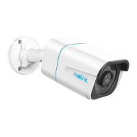
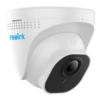
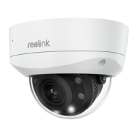
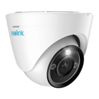
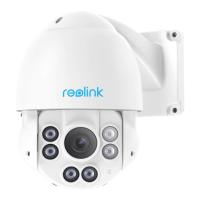
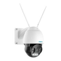
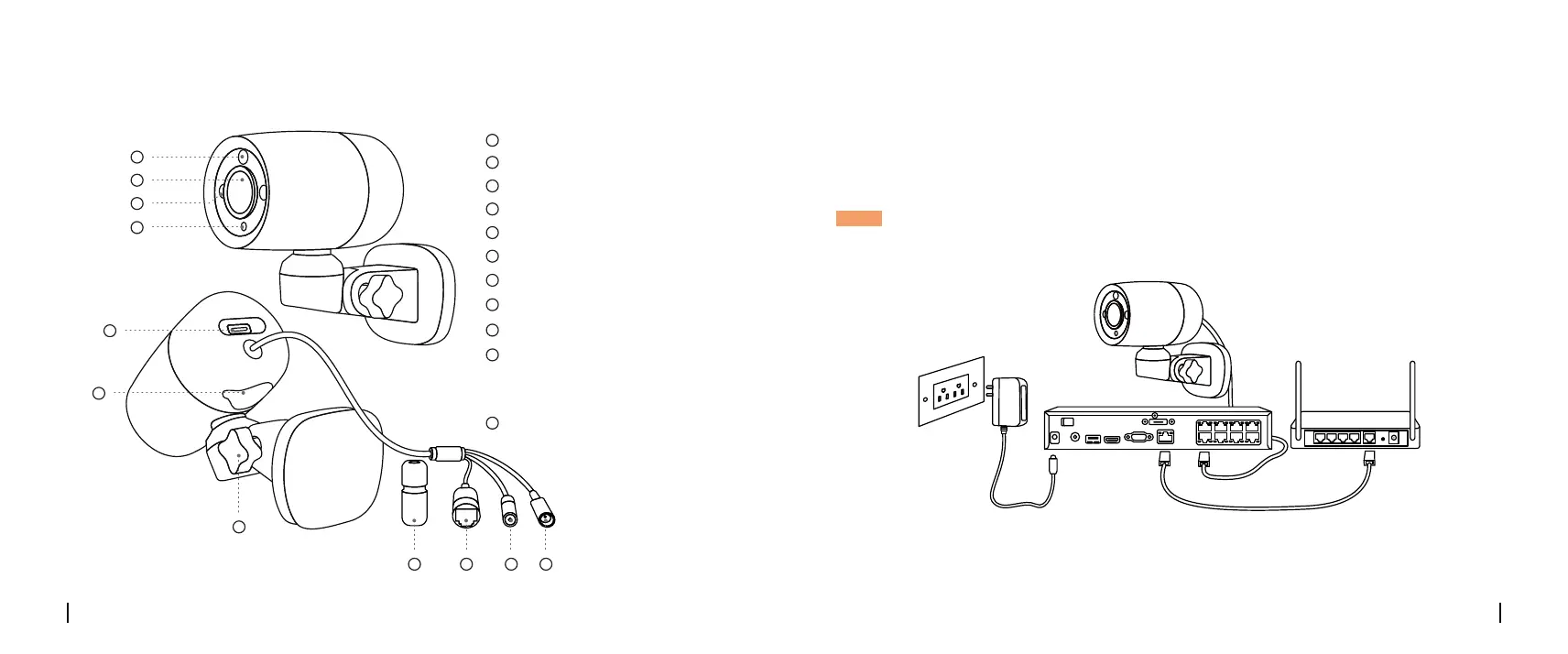
Camera Introduction
Spotlight
Micro SD Card Slot
IR LEDs
Lens
Speaker
Adjustment Knob
Network Cable
Power Port(Optional)
Waterproof Lid
Reset Button
* Press for about 10 seconds to
restore the device to factory
settings.
Daylight Sensor
1
2
3
4
5
6
7
9
11
8
10
1
4
5
6
7
8 9 10 11
2
3
Connection Diagram
Before using the camera, please connect your camera as instructed
below to finish initial setup.
1. Connect the camera to a Reolink NVR (not included) with an Ethernet cable.
2. Connect the NVR to your router, and then power on the NVR.
* You may also connect the camera to a PoE switch or PoE injector.
NOTE: The camera should be powered with a 12V DC adapter or a PoE powering device such as
PoE injector, PoE switch or Reolink NVR (not included in the package).
PoE IP Camera
Ethernet Cable
Reolink NVR Router
Ethernet Cable
Power Adapter

 Loading...