10
RBC16SS3
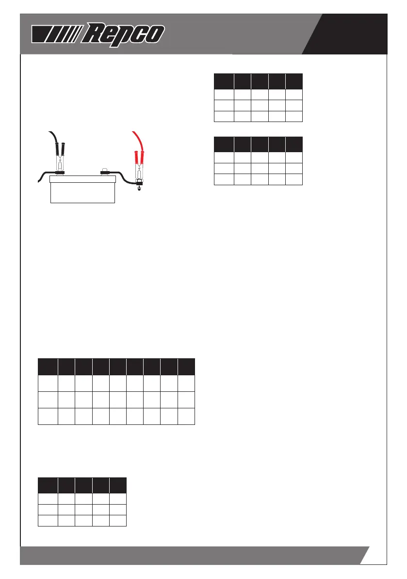
Positively Earthed
Connect the NEGATIVE (BLACK) lead/battery
clamp from the battery charger to the Negative
(-) battery terminal. Connect the POSITIVE (RED)
lead/battery clamp from the battery charger to
the vehicle’s chassis - away from the fuel lines or
moving parts.
+
-
+
-
STEP 4 - CONNECT TO MAINS POWER
Connect the battery charger to a 240V mains
powered socket, turn on the mains power and
press the “ON/OFF” button. The POWER LED and
the Liquid Crystal Display (LCD) will illuminate
to confirm that the Battery Charger is receiving
power.
STEP 5 - SELECT THE CHARGE VOLTAGE
Press the “SELECT” button to select the
appropriate battery voltage - 6V or 12V.
The LCD will display 6P or 12P.
STEP 6 - SELECT THE CHARGE RATE
Using the table below, determine the charge rate
for the battery to be charged and press the “RATE”
button to select the appropriate CURRENT (A)
setting.
AMPS
CCA
min
CCA
max
MCA
min
MCA
max
Ah
min
Ah
max
RC (A)
min
RC (A)
max
2 80 270 110 330 12 40 22 65
8 270 1000 380 1300 45 160 75 270
16 630 1900 880 2700 105 320 175 550
OPTIMUM CHARGE RATE SETTINGS
The following tables provide the recommended
“Charge Rate” setting for the battery “chemistry”
and battery size/capacity.
Wet (Lead Acid)/Calcium
AMPS CCA MCA Ah RC (A)
2 120 150 20 33
8 480 600 80 130
16 960 1200 160 260
AGM/Gel
AMPS CCA MCA Ah RC (A)
2 60 75 10 17
8 240 300 40 68
16 480 600 80 136
VRLA
AMPS CCA MCA Ah RC (A)
2 48 65 8 13
8 192 260 32 52
16 384 520 64 104
Note - If your battery is between the battery
capacity’s, select the next highest setting.
STEP 7 - SELECT THE BATTERY CHEMISTRY
Press the “TYPE” button to select the appropriate
battery chemistry and technology - WET,
CALCIUM, AGM, or GEL.
Note - if the battery charger does not detect
a properly connected battery, or detects an
incorrect battery voltage, the “Er1” or “Er4”
will display on the screen and charging will not
commence.
STEP 8 - CHARGING
The CHARGING LED will illuminate and the voltage
being supplied to the battery is displayed in the
LCD window.
STEP 9 - MONITORING
During charging cycles, voltage (V), current (A)
or percentage charged (%) can be displayed on
the LCD by pressing the “MODE” button. After
approximately 5 seconds, the LCD display will
revert to voltage (V).
Note - During the charge cycle, voltages up to
15.8V (7.9V in 6V MODE) may be observed - this is
deemed normal.
STEP 10 - CHARGING COMPLETE
Once charging of the battery is complete, the
CHARGING LED will extinguish, the CHARGED
LED will illuminate and FUL will display in the
LCD window for 2 minutes. At this point, the RED
LCD will extinguish and the Green CHARGED and
POWER LED’s will continue to illuminate to show
that the battery is charged..
Note - If at any stage during charging, the battery
is found to be faulty, Er2 will be displayed and
charging will terminate.
STEP 11 - DISCONNECTION
Once charging is completed and FUL is displayed
in the LCD window. BEFORE removing the battery
 Loading...