Do you have a question about the Repco RBC25SS3 and is the answer not in the manual?
Lists critical safety precautions including handling explosive gases, proper ventilation, and personal protection.
Covers Microprocessor Technology, Desulphation, Reconditioning, and Automatic Multi-Cycle Conditioning features for optimal battery care.
Details benefits like Maximising Battery Performance, Maximising Battery Life, and Automatic Microprocessor Control.
Explains the LCD Display/Backlight and Voltage Display functionalities for user interaction and monitoring.
Covers initial battery evaluation and preparation stages including diagnosis, desulphation, pre-charge, and soft start.
Details the Bulk Charge (Constant Current) and Absorption (Constant Voltage) phases for efficient charging.
Explains the analysis, recondition (high voltage repair), and maintain stages for optimal battery condition.
Details requirements for indoor, cool, dry, well-ventilated placement away from flammables and ignition sources.
Explains the meaning of LCD displays like ER1, ER2, FUL, and various battery charge condition indicators.
Covers battery manufacturer recommendations and electrolyte level checks before connecting.
Details connecting the charger to batteries, both in and out of the vehicle, including polarity considerations.
Instructs on connecting the charger to the mains power supply and activating it.
Addresses ER1 (connection error) and ER2 (bad battery) and issues with no output.
Explains clicking sounds, why batteries may not accept charge, and the definition of a faulty cell.
Clarifies that the charger cannot be used as a power supply.
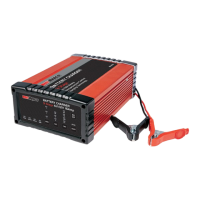
This document describes the Repco 9 Stage Battery Charger, available in models RBC25SS3 and RBC5SS3, designed for efficient and safe charging of various lead-acid battery types.
The Repco 9 Stage Battery Chargers are intelligent, automatic devices that utilize microprocessor technology to efficiently charge most lead-acid battery types, including Wet, AGM, Gel, VRLA, and Calcium* batteries. These chargers are designed to maximize battery performance and extend battery life by cycling through a sophisticated 9-stage charging process. This unique system can repeat the charging cycle up to three times to recondition and recharge batteries that are in poor condition or have been left idle for prolonged periods, potentially saving the cost of an expensive battery replacement. The chargers convert 240VAC to 12VDC charging power using electronic components, making them lightweight and compact without sacrificing performance. For safety, polarity protection prevents sparking from accidental reverse connections or short circuits.
The charging process begins with a Diagnosis stage, where the charger checks the connection and evaluates the battery. If the connection is incorrect or the battery is faulty, an error message (Er1 or Er2) will be displayed, and charging will not proceed. If connections are correct and a chargeable voltage is identified, the charger moves to the next stage.
The Desulphation stage applies a stepped or pulsed voltage to help remove sulphation from the battery plates. Sulphation can occur when batteries are left discharged for extended periods and hinders the battery's ability to accept a charge, reducing its service life. Regular charging helps minimize sulphation.
Following this, the Pre-Charge stage uses a low voltage and current to slowly improve battery condition and enhance electrolytic consistency, which can become uneven with daily use.
The Soft Start stage gradually increases voltage and current over time to control heat, reduce gassing, and minimize battery stress.
The Bulk Charge (Constant Current) stage is divided into three sub-stages:
The Absorption (Constant Voltage) stage applies an even higher voltage while gradually reducing current. This ensures the battery is fully topped up without being overcharged.
Next, the Analysis stage assesses the battery's discharge rate over a period. Based on this performance, the charger decides whether to recommence charging or move to the final stage.
If required, a Recondition (High Voltage Repair) phase applies maximum voltage to optimize battery condition and repair plates. This stage is particularly useful after significant discharge, for batteries with uneven cell capacity, or to alleviate acid stratification in Calcium batteries left discharged for more than a couple of days. The charger will assess the battery's condition and may not perform this function if not needed.
Finally, the Maintain stage monitors the battery voltage and recommences the charge sequence if the voltage drops below a certain threshold (12.8V for 12V batteries or 6.4V for 6V batteries), ensuring the battery remains ready for use.
The Repco Battery Chargers are designed for indoor use and should not be exposed to rain. They are suitable for charging 6V and 12V rechargeable lead-acid automotive-type batteries. The charger is not intended for non-rechargeable batteries or other battery types like Nickel Cadmium (NiCad), Nickel-Metal Hydride (Ni-MH), or Dry-Cell. It should never be used to charge a frozen battery.
The charger features an LCD display with a backlight, providing clear and easy-to-read information, even in low light. The display shows the actual battery voltage before selecting a "CHARGE OPTION" and the voltage being applied during charging. Error messages (ER1 for incorrect connection/voltage, ER2 for damaged/unrecoverable battery) and "FUL" (for fully charged) are also displayed. Batteries with a voltage below 10.5V (5.2V for 6V) may be permanently damaged, so it's recommended not to discharge them below these levels.
The charger offers automatic multi-cycle conditioning. If a battery does not hold charge after the first cycle, the 9-stage cycle is automatically repeated up to two more times to achieve maximum charge, reducing the need for manual monitoring.
Connection Procedure:
The charger is designed to be left connected to the battery without risk of overcharging. Once full, it automatically monitors the battery and tops it up as needed, ensuring it's always ready. If left connected, the charger will maintain the battery, preventing slow discharge.
The Repco Battery Chargers are designed for durability and ease of use. For permanent installations, mounting holes in the flanges allow for quick and easy mounting. When installed in caravans, motorhomes, or 4WDs, the charger should be mounted in a well-ventilated location, protected from rain, water, or moisture.
To minimize TV/Radio interference, position the charger away from TVs, radios, antennas, and antenna cables.
Safety Warnings:
The charger incorporates reverse polarity and short circuit protection, making it safer to use. It will only output power when connected to a battery exhibiting a voltage above 2 volts (2V), preventing it from being used as a general 'Power Supply'. A "clicking" sound during operation is normal, as it indicates the microprocessor relay switching between stages.
If a battery does not accept a charge, check the voltage selection and allow sufficient time for charge cycles (up to 48 hours). If the "ERROR" LED illuminates after charging, a faulty cell might be present. 12V batteries have 6 cells (6V batteries have 3 cells), and one faulty cell can ruin the battery. Testing cells with a hydrometer can identify a faulty cell; if one reading is lower than the rest, the battery needs replacement.
| Output Current | 25A |
|---|---|
| Charge Rate | 25A |
| Input Voltage | 230-240VAC |
| Output Voltage | 12V |
| Battery Type | Lead Acid |
| Protection Features | Reverse Polarity, Over Voltage, Over Current, Over Temperature, Short Circuit |