04
05
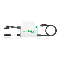
Step 2 - Connect the Replus-250/ Replus-250A/B Cable
Each Replus-250/ Replus-250A/B comes with one 3-pin bulkhead receptacle (or short pigtail) and
one 57-inch AC wire harness with mul-pin connectors. (The DC input wires are approximately six
inches long and are terminated with single pole connectors.) The AC connectors are oppositely
sexed, so that mulple inverters can be connected to form one connuous AC branch circuit.
1. Orient the first Replus-250/ Replus-250A/B in each branch with its male connector facing the
juncon box. The juncon box AC interconnect cable has a female connector. The Replus-250/
Replus-250A/B can be mounted with either side facing up to accommodate cable roung.
Connect the first Replus-250/ Replus-250A/B to the AC interconnect cable.
2. Plug the AC connector of the first Replus-250/ Replus-250A/B into the connector of the next
Replus-250/ Replus-250A/B, and so forth, to form a connuous AC circuit. Please check the
Replus-250/ Replus-250A/B rang label for the maximum allowable number of Replus-250/
Replus-250A/B’s on one AC circuit.
Warning: Do Not Exceed The Maximum Number Of Replus-250/ Replus-250a/b’s In An Ac
Branch Circuit, As Displayed On The Unit-rang Label. Each Replus-250/ Replus-250a/b Ac
Branch Circuit Must Be Sourced From A Dedicated Branch Circuit Protected By A 15a
Maximum Breaker.
3. Install a protecve end cap on the open AC connector of the last Replus-250/ Replus-250A/B in
the AC branch circuit.
Warning: Make Sure Protecve End Caps Have Been Installed On All Unused Ac Connectors.
Unused Ac Replus-250/ Replus-250A/B Wire Harness Connectors Are Live When The System
Is Energized By The Ulity System.
Step 3 - Install the AC Branch Circuit Juncon Box
1. Measure service entrance conductors to confirm AC service at the site. Acceptable ranges are
shown in the table below:
2. Mount the adapter plate at a suitable locaon on the PV rack system (typically at the end of a
row of modules).
3. Install an appropriate juncon box with the adapter plate.
4. Connect the open wire end of the AC interconnect cable into the juncon box using an
appropriate cable.
1. Mark the approximate centers of each PV module on the rack system. Evaluate the locaon of
the micro inverter with respect to the PV module juncon box or any other obstrucons.
Warning: Allow A Minimum Of 0.75 Inches Between The Top Of The Roof And The Boom Of
The Replus-250/ Replus-250a/b. We Also Recommend That You Allow 0.5 Inches Between The
Back Of The Pv Module And The Top Of Replus-250/ Replus-250a/b. Do Not Mount Replus-250/
Replus-250a/b In A Locaon That Allows Long-term Exposure To Direct Sunlight.
2. If using grounding washers to ground the micro inverter chassis to the PV module rack, choose
a grounding washer that is approved for the rack manufacturer. Install a minimum of one
grounding washer per micro inverter. Tear down barcode from inverter, paste the barcode into
the “Connecon map”. Torque the micro inverter fasteners to the values listed below.
1/4” mounng hardware – 45 in-lbs minimum
5/16” mounng hardware – 80 in-lbs minimum
Warning: Do Not Connect Replus-250/ Replus-250A/B To The Ulity Grid Or Energize The Ac
Circuit(S) Unl You Have Completed All Of The Installaon Procedures As Described In The
Following Secons.
Installing the Replus-250/ Replus-250A/B micro inverter System involves several key steps:
1. Aaching the Replus-250/ Replus-250A/B micro inverter to the rack.
2. Connecng the Replus-250/ Replus-250A/B micro inverter wiring harnesses.
3. Measuring service and installing the AC branch circuit juncon box.
Warning: Only Use Electrical System Components Approved For Wet Locaons.
4. Grounding the system.
5. Compleng the Replus-250/ Replus-250A/B micro inverter installaon and connecng the PV
modules.
The finished system should be similar as in the diagram. Detailed installaon steps are listed in the
following secon.
Installaon Procedure
Step 1 - Aach the Replus-250/ Replus-250A/B to the Rack
3. Mount one micro inverter at each of these locaons using hardware
recommended by your module rack vendor. Mounng slots on the micro
inverter are 0.33 inches in diameter. Maximum bolt size is 5/16 inch.
The two slots on the micro inverter are 4 inches apart
240 Volt AC Split Phases 208 Volt AC Three Phases 230 Volt AC Single Phase
L1 to L2 211 to 264 Vac L1 to L2 183 to 229 Vac
L1 to L2 200 to 270 Vac
L1, L2 to neutral 106 to 132 Vac L1, L2 to neutral 106 to 132 Vac
 Loading...