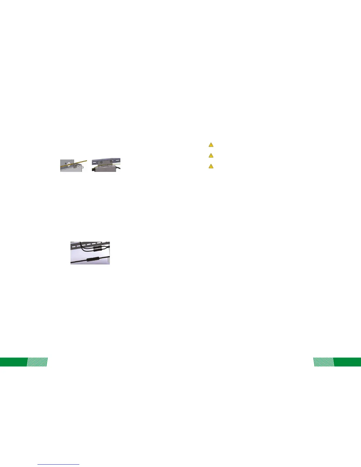
Step 4 – Ground the System
Each Replus-250/ Replus-250A/B comes with a ground clip that can accommodate a 6-8 AWG
conductor. The rack and module could be grounded to this conductor using a crimp connecon.
An alternave method would be to connect the Replus-250/ Replus-250A/B to the grounded rack
using a grounding washer approved for the rack.
Completely install all Replus-250/ Replus-250A/B and system inter-wiring connecons prior to
installing the PV modules.
1. Mount the PV modules above the corresponding Replus-250/ Replus-250A/B. Each
Replus-250/Replus-250A/B comes with two oppositely sexed DC connectors.
2. First connect the posive DC wire from the PV module to the negavely marked DC connector
(male pin) of the Replus-250/ Replus-250A/B. Then connect the negave DC wire from the PV
module to the posively marked DC connector (female socket) of the Replus-250/
Replus-250A/B. Repeat for all remaining PV modules using one Replus-250/ Replus-250A/B for
each module.
Step 5 - Connect the PV Modules and Complete the connecon map
Connect the PV Modules
The Replus-250/ Replus-250A/B Connecon Map is a diagrammac representaon of the
physical locaon of each Replus-250/ Replus-250A/B in your PV installaon. The virtual array in
the ReneSola micro inverter gateway, MRG, is created from the map you create.
Each Replus-250/ Replus-250A/B has a serial number, enter this serial number into the MRG
according with barcode of “connecon map”, so MRG can correspond with micro inverter and
internet.
Complete Connecon Map
Warning: Connectreplus-250/ Replus-250a/b To The Electrical Ulity Grid Only Aer
Receiving Prior Approval From The Ulity Company.
Warning: Be Aware That Only Qualified Personnel Must Connect Replus-250/
Replus-250a/b To The Electrical Ulity Grid.
Warning: Ensure That All Ac And Dc Wiring Is Correct. Ensure That None Of The Ac And Dc
Wires Are Pinched Or Damaged. Ensure That All Juncon Boxes Are Properly Capped And Not
Exposed.
Following these steps to commission the Replus-250/ Replus-250A/B PV system:
1. Turn ON the AC disconnector or circuit breaker on each Replus-250/ Replus-250A/B AC branch
circuit.
2. Turn ON the main ulity-grid AC circuit breaker. Your system will start producing power aer a
few minutes wait me.
3. The Replus-250/ Replus-250A/B will start to send performance data over the power lines using
power line communicaon (PLC) to the MRG. The me required for each Replus-250/
Replus-250A/B in the system to communicate to the MRG will vary with the number of
Replus-250/ Replus-250A/B’s in the system.
Status: standby
5. COMMISSIONING
6. OPERATING INSTRUCTIONS
The Replus-250/ Replus-250A/B is powered on when sufficient DC voltage from the module is
applied. The status LED will start flashing aer sufficient DC power is applied as an indicaon that
the Replus-250/ Replus-250A/B is live.
The LED light is on by 2 seconds, and off by 2 seconds.
Status: producing power
The LED light is on by 1 second, and off by 1 second.
Status: producing power and communicang with MRG
The LED light is on by 0.5 second, and off by 0.5 second.
06
07