11 |
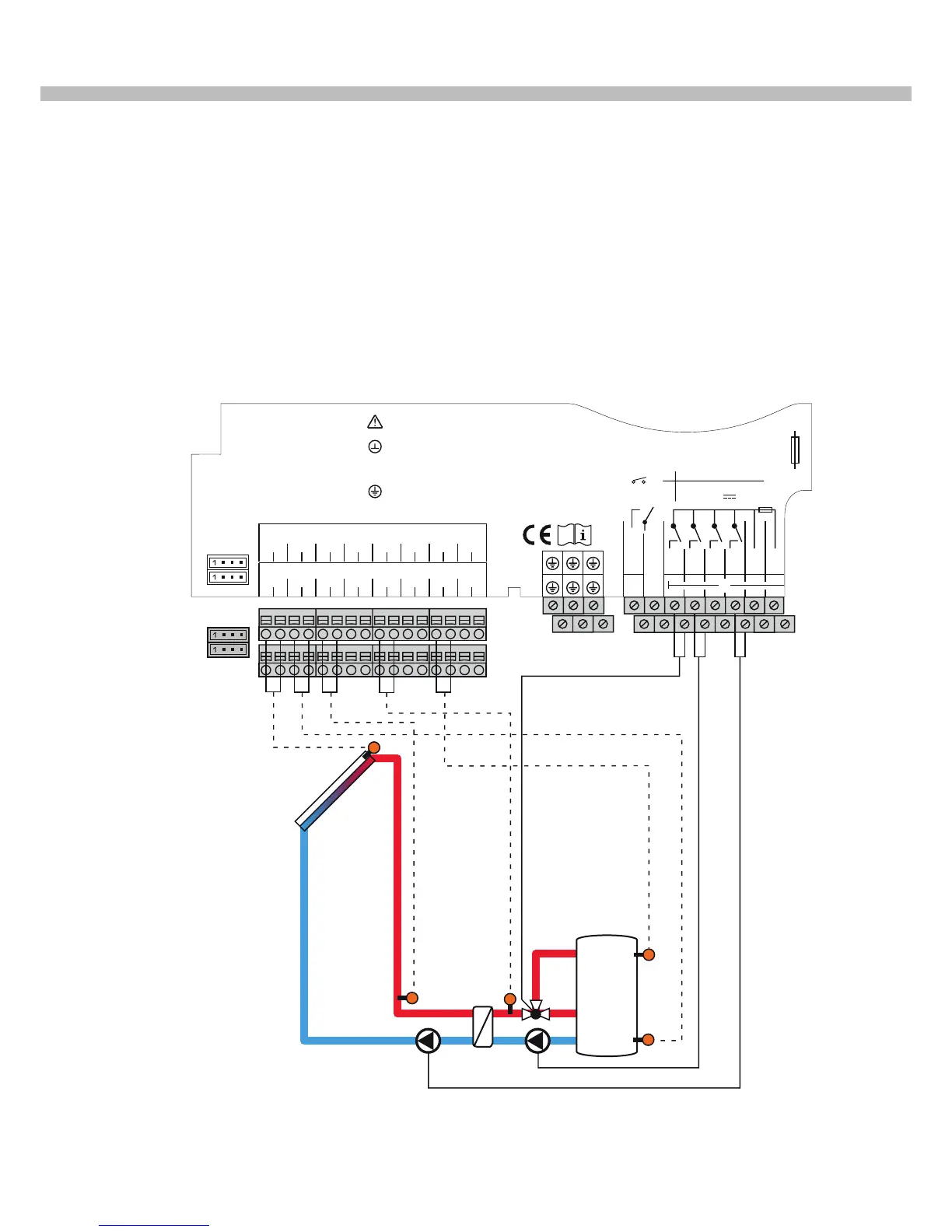
The controller compares the temperature at collector sen-
sor S1 with the temperature at store sensor S2 (store 1).
If the temperature difference measured is higher than the
adjusted switch-on temperature difference, the pump (R1)
will be activated; the solar circuit will be heated.
The pump speed is controlled such that the adjustable tem-
perature difference is reached. If the temperature differ-
ence between S3 and S2 exceeds the adjusted switch-on
temperature difference for the secondary pump (external
heat exchanger), the secondary pump (R3) will be switched
on. Store loading is controlled by means of an additional
heat exchange function. The valve (R4) is normally open to
load the central store zone.
If the temperature difference between S5 and S7 exceeds
the switch-on temperature difference, the upper store
zone will be loaded up to the adjusted set temperature.
S3
S1
S5
S7
(V1)
R4
R3
R1
S2
S1
1234 5678910 11 12 13 14 15 16
S2 S3 S4 S5 S6 S7 S8
R4
R5
IP20
R5
N
R1-R4
100 ... 240 V~
50-60 Hz
T4A
1 (1) A (100 ... 240) V~
4 (1) A 240 V~
4 (1) A 24V
R5
R3
R2
R1
L' L
Temp. Sensor
RPD
N
Isolate mains before removing cover!
Vor Öffnen Gerät spannungslos schalten!
Use ground common terminal block
Masse-Sammelklemme benutzen
Use neutral conductor common terminal block
Neutralleiter-Sammelklemme benutzen!
Use PE Common terminal block
Schutzleiter-Sammelklemme benutzen
VFD
S9
V40
S10
V40
PWMA
0-10V
PWMB
0-10V
PWMC
0-10V
PWMD
0-10V
17 18 19 20 21 22 23 24 25 26 27 28 29 30 31 32
CS10 VBus
DeltaSol
®
BX+ V2
KIOTO Clear Energy AG
A - 9300 St. Veit a.d. Glan
Speicher
1
1. System description stratified layer module basic scheme (Scheme number 001 / 011)
Note: In scheme 011, connect the pump R1 to PWM A and R3 to PWM C additionally.
Store 1
 Loading...