www.restek.com 3
Restek Electronic Leak Detector
Operating Instructions
1.0 Introduction
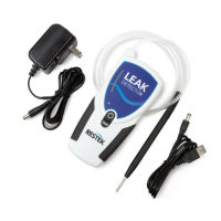
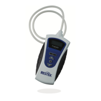
Restek’s portable electronic leak detector is specifically designed for use with gas chromatography (GC) sys-
tems. It detects small leaks of any gas with a thermal conductivity different from air. The reference gas inlet
(Figure 1) draws in ambient air for comparison to gas drawn into the sample probe. The intensity of a leak is
indicated by both an LED light display and an audible alarm. The following table explains how to interpret the
LED display.
NOTE: The leak detector is not a quantitative device, it is a qualitative measure of the location, intensity, and
nature of a gas leak.
It is best practice to use a leak detector daily to check critical seals (for example, septa, column nuts, reduc-
ing nuts, and fittings on gas lines). In addition to being used regularly, the leak detector should be charged
regularly to ensure the battery pack continues to hold its charge.
If this instrument is used in any manner other than described in the manual, the CE declaration is void.
The leak detector is manufactured by Restek and is backed by our 100% satisfaction guarantee.
Should you require assistance at anytime regarding our leak detector, please contact Restek Customer Service.
Leak Detector LED Indicator Display and Interpretation
Unit State - Powered
On/Off
LED Color LED State Interpretation
Unit Battery
State
On
Blue > Red
& Yellow
On/Blue flashes once, red and
yellow cycle for 15 seconds/Off
Unit is powering on and
running startup sequence
On Blue On/Steady
Ready for use, battery does not
require charging
On Blue On/Constant Flashing IMPORTANT: Unit must be charged
Power Button
Depressed
NONE NONE
Battery has fully discharged,
charge immediately
Unit Charging
State
On/Off Green On/Flashing
Unit is plugged in to the AC adaptor or
USB cable and is charging a very
low battery (trickle charging)
On/Off Green On/Steady
Unit is plugged in to AC adaptor or
USB cable and is in full charge mode
On/Off Green Off
Unit is plugged into AC adaptor or
USB cable and the unit is fully charged
Unit Operation
On
Red or
Yellow
On/Steady
Unit is indicating a difference in thermal
conductivity between probe and reference
On
Red &
Yellow
On/Cycling for 4
seconds/Off
Zero set button has been depressed
and unit is rezeroing
 Loading...