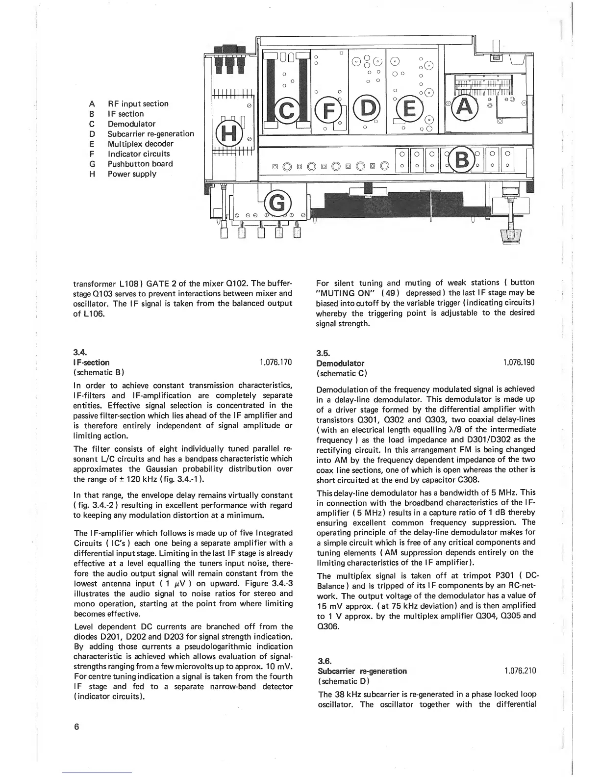
A RF
input
section
B
I F
section
C
Demodulator
D
Subcarrier
re-generation
E
Multiplex
decoder
F
Indicator
circuits
G
Pushbutton
board
H
Power
supply
transformer
L108
)
GATE
2
of the
mixer
Q102.
The
buffer-
stage Q103
serves to
prevent
interactions
between
mixer
and
oscillator.
The
IF
signal is
taken
from the
balanced
output
of
L106.
For silent
tuning
and
muting
of
weak
stations
(
button
"MUTING
ON"
(
49
)
depressed
)
the
last
IF stage
may
be
biased
into
cutoff
by
the
variable
trigger
(indicating
circuits)
whereby
the
triggering
point is
adjustable
to
the
desired
signal
strength.
3.4.
I
F-section
1.076.170
(schematic B)
in order
to
achieve constant
transmission
characteristics,
IF-filters and
IF-amplification are
completely
separate
entities. Effective signal
selection
is concentrated
in the
passive filter-section which
lies ahead
of
the
IF amplifier and
is therefore entirely
independent
of signal amplitude
or
limiting action.
The
filter consists
of
eight
individually
tuned
parallel re-
sonant
L/C
circuits and has a
bandpass
characteristic
which
approximates the Gaussian
probability
distribution
over
the range of
±
1
20
kHz
(fig.
3.4.-
1
).
In that range,
the envelope delay remains virtually constant
(
fig.
3.4.-2
)
resulting in excellent performance with regard
to keeping any
modulation distortion at
a
minimum.
The I F-amplifier which
follows is made up
of five Integrated
Circuits
(
IC's
)
each
one being a
separate
amplifier with
a
differential
input stage. Limiting
in the last
I
F
stage is already
effective at a
level equalling the
tuners
input
noise, there-
fore
the audio
output signal will
remain constant
from
the
lowest antenna
input
(
1
juV
)
on
upward.
Figure
3.4.-3
illustrates
the
audio
signal
to
noise
ratios
for stereo and
mono operation, starting at the
point
from where
limiting
becomes
effective.
Level
dependent
DC
currents
are branched
off
from
the
diodes D201, D202 and D203
for signal strength Indication.
By
adding those currents
a
pseudologarlthmic Indication
characteristic is
achieved which allows evaluation
of
signal-
strengths ranging from
a few microvolts
up
to approx.
1
0
mV.
For
centre tuning
indication
a
signal is
taken from
the fourth
IF
stage and fed
to a separate
narrow-band
detector
(indicator
circuits).
3.5.
Demodulator
1
.076. 1 90
(schematic C)
Demodulation
of
the
frequency
modulated
signal Is
achieved
in a
delay-line
demodulator.
This
demodulator
Is made
up
of a
driver
stage
formed
by
the
differential
amplifier
with
transistors
Q301,
Q302
and
Q303,
two
coaxial
delay-lines
(
with an
electrical
length
equalling
X/8
of the
intermediate
frequency
)
as
the
load
impedance
and
D301/D302
as
the
rectifying
circuit,
in this
arrangement
FM
is
being
changed
into
AM
by
the
frequency
dependent
impedance
of the
two
coax
line
sections,
one
of which
is open
whereas
the
other
is
short
circuited at
the
end
by
capacitor C308.
This
delay-line
demodulator has
a
bandwidth
of
5
MHz.
This
in
connection
with the
broadband
characteristics
of the
IF-
amplifier
(
5
MHz)
results
in
a
capture
ratio
of 1 dB
thereby
ensuring
excellent
common
frequency
suppression.
The
operating
principle of the
delay-line demodulator
makes
for
a
simple
circuit which
is free
of any critical
components
and
tuning elements
(
AM
suppression depends
entirely
on
the
limiting
characteristics
of
the
IF
amplifier).
The
multiplex
signal is
taken
off at
trimpot
P301
(
DC-
Balance
)
and
is
tripped
of its
I
F
components by
an RC-net-
work. The
output
voltage
of the demodulator
has a
value
of
15
mV
approx. (
at
75
kHz
deviation) and
is
then
amplified
to 1 V
approx, by
the
multiplex
amplifier
Q304,
Q305
and
Q306.
3.6.
Subcarrier
re-generation
1.076.210
(schematic D)
The
38
kHz subcarrier
is re-generated
in
a
phase
locked
loop
oscillator. The
oscillator together
with the
differential
6