Do you have a question about the Revox B261 and is the answer not in the manual?
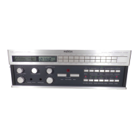
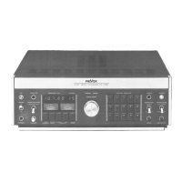
Identifies and describes front panel controls like power, tuning, station selection, and memory.
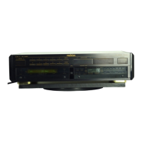
Details the function of each connector on the rear panel.
Lists essential test equipment and tools for servicing.
Procedures for removing the top, bottom, side, and front panels.
Instructions for replacing meter illumination lamps and internal fuses.
Steps for removing meters, display, keyboard, and contact pad.
Procedure for removing the power supply assembly and its PCB.
General guidance for reassembling the unit after servicing.
Description of the power supply unit, transformer, and PCB.
Explanation of the RF input, antenna switch, and synthesizer circuitry.
Description of IF amplifier, demodulator, and related filters.
Explanation of the stereo decoder circuit.
Description of the audio section and the microcomputer control unit.
Details the keyboard, display, level controls, and remote receiver.
Procedure for adjusting the +33V power supply voltage.
Procedure for adjusting the synthesizer's tuning voltage.
Procedure for aligning the RF amplifier stage.
Procedure for aligning the IF amplifier stages.
Procedures for adjusting the demodulator and discriminator.
Alignment procedures for the stereo decoder, including oscillators and filters.
Procedures for aligning the audio PCB and the display unit.
Details reception range, sensitivity, and rejection ratios.
Covers frequency response, distortion, S/N, and stereo separation.
Physical dimensions, power, operating conditions, and options.
Diagram showing numbered front panel components.
Comprehensive list of parts for the operating section.