sT[JDtrR
Rd/OX
8261 SA
sEciloN
4/8x
4.7.8 Adjusting the 10
kHz cross-talk rejection
-
Set stereo standard-signal-
generator
to 98.0
MHz,
40 k}Jz
deviation, modulation
1"0 kHz
(left
=
right),
modulate
onJ-y
right-hand channel of stereo
modulator,
and
adjust for maximum
cross-tal-k
rejection
with
L6
(<40
dB).
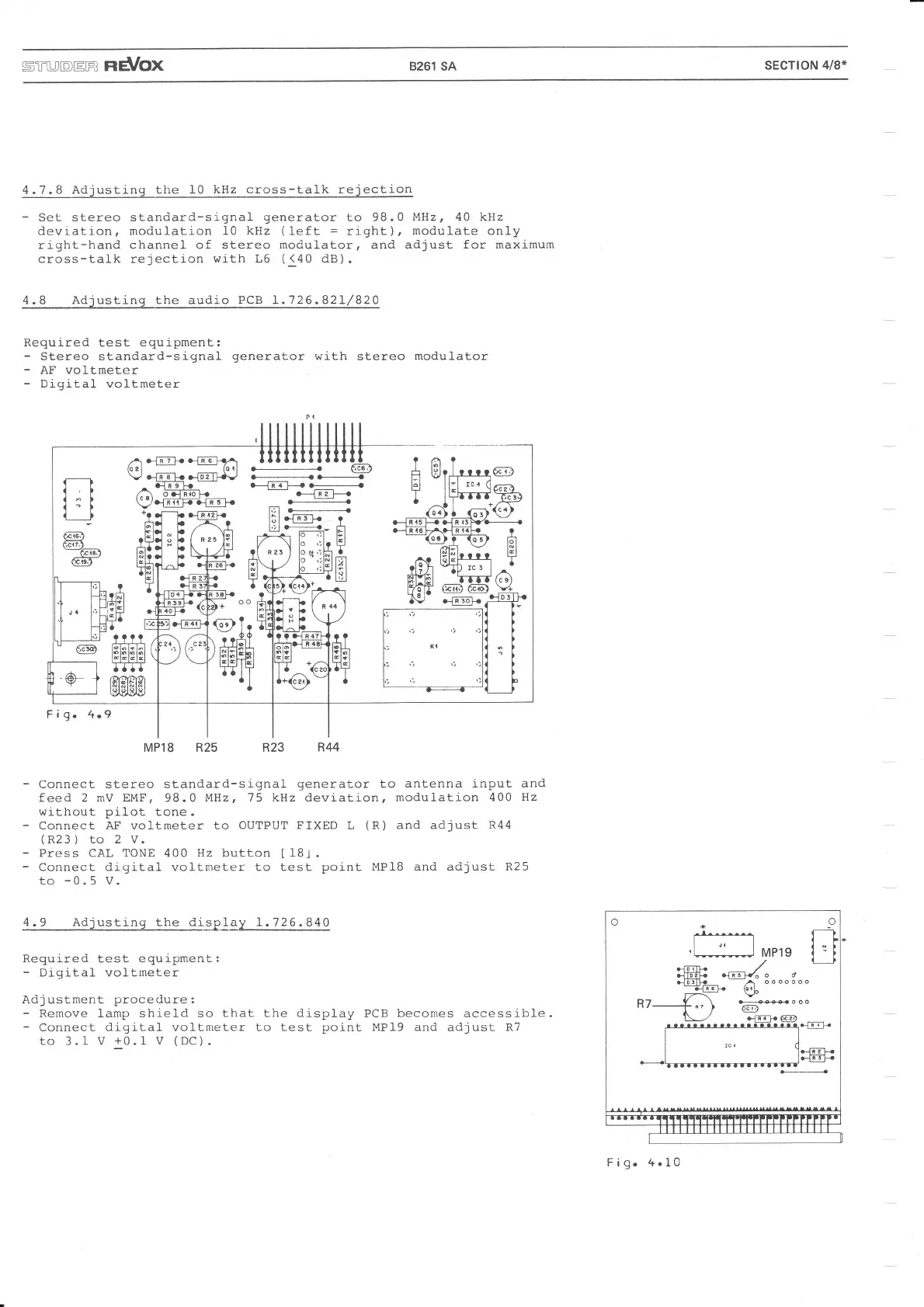
4.8 Adjusting the audio PCB 1.726.821,/820
Required
test equipment:
-
Stereo standard-signal
generator
with stereo
modulator
-
AF voltmeter
-
Digital
voltmeter
.-..1
,l
I
(.f
a')
T-L
@
Ccr7.l
-6G:)
@-
A .-]T?L }li-F}.A
lo?l {orl
V
G.b
8
t!
G{gr
Ll}t
^
.f-Lc-E-
/ \ odRroh
\7.l_U!{
}13
g
}-
H
HH
o--_1-ÄT]<-
-e{F
.+
l::l t-+
l;l>L!lF ?
Lil:ö
JI3"ILIF
til
lal
M
Fig.
4.9
MP18 R25 R23
-
Connect stereo standard-signal
generator
to
antenna input and
feed 2 mV EMF, 98.0
MHz, 75 kHz deviation, modulation
400 Hz
without
pilot
tone.
-
Connect AF voltmeter to OUTPUT
FIXED
L
(R)
and adjust
R44
(R23)
to 2 V.
-
Press CAL
TONE
400 Hz button
[181.
-
Connect
digital voltmeter to test
point MP18 and
adjust
R25
to
-0.5
V.
4.9 Adjusting
the
display 1.726.840
??t?
tlta
r&ß(gla
lglälgtgj
R44
Required
test equipment:
-
DigitaJ- voltmeter
Adjustment
procedure:
-
Rernove larnp shield so that the display
-
Connect digi-tal voftmeter
to
test
point
to 3.I V
+0.1-
V
(DC).
PCB
becomes
accessible
MP19 and
adjust
R7
t,,t
,l---------l
MP19
,/
dDrlb a
.JTtiL. .1 e-äf</^ o d
!nrlb
NjlF
(crL
l^v-
AY
R7----+
",
\
...'-*ooo
i/
1\_-./ {n-Tt- GID
Fig.
4.10