Do you have a question about the Revox A76 and is the answer not in the manual?
Steps to remove the front panel by pulling knobs and fasteners.
Steps to remove the chassis from the cabinet after removing screws and spacers.
Instructions for lacing the dial cord using steel wire and nylon cord.
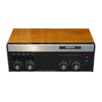
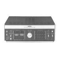
Identifies operating controls by index numbers matching the Operating Instructions.
Lists the available schematics (block, interconnecting, complete circuit diagrams).
Describes the RF input stage, including FET and mixer components.
Details the IF section with passive filters and integrated amplifier circuits.
Explains the delay-line demodulator and its components for FM signal processing.
Describes the 38 kHz subcarrier regeneration using a phase locked loop oscillator.
Explains the switching principle of the multiplex decoder for channel separation.
Covers auxiliary circuits for tuning indication and automatic functions like muting.
Details the power supply section with electronically regulated voltage outputs.
Lists the required test equipment for alignment procedures.
Lists necessary tools and filters for measurements and adjustments.
Outlines the procedure for checking supply voltages before alignment.
Instructions for tuning the IF filters for maximum output voltage.
Procedure for aligning the center tuning discriminator after IF filter tuning.
Method for checking bandwidth and static selectivity of the tuner.
Steps to align the RF input section and oscillator circuits.
Instructions for aligning the IF amplifier transformer coupling.
Procedure to check and correct the symmetry of the center tuning meter.
Steps to verify correct limiting action in the IF amplifier.
Checks the sensitivity of the tuning and signal strength meters.
Procedure for aligning the FM demodulator for minimum distortion.
Steps to align the multipath indicator circuit.
Procedure to tune the 76 kHz subcarrier oscillator coil.
Steps to adjust the 19 kHz circuit and check the stereo indicator.
Procedure to tune the 38 kHz circuit for envelope crossover.
Instructions for tuning the 19 kHz band pass filter for envelope crossover.
Procedure to adjust multiplex filters for minimum MPX-signal.
Steps to adjust for minimum stereo crosstalk between channels.
Verifies the automatic mono-stereo changeover function.
Checks the function and attenuation range of output potentiometers.
Measures input sensitivity for mono and stereo modes.
Refers to section 4.6.6 to 4.6.7 for static selectivity measurement.
Measures the tuner's image response performance.
Measures the tuner's spurious response characteristics.
Measures the total harmonic distortion in mono mode.
Measures the signal to noise ratio.
Measures the stereo separation or crosstalk between channels.
Measures the frequency response across different modulating frequencies.