STI'DtrR
]IEVOX
8261
SA
SECTION 4/2
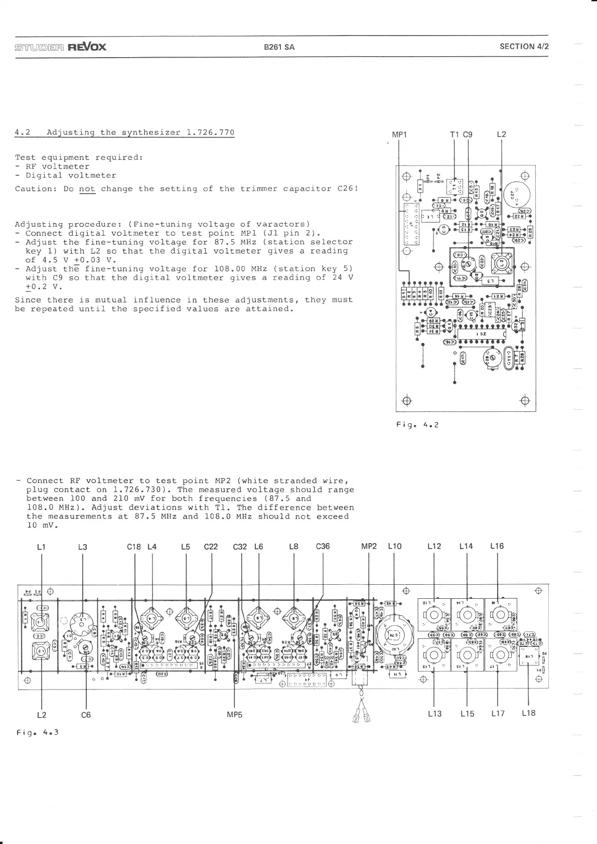
4.2 Adiustinq
the synthesizer 1.126.770
Test
equipment required:
-
RF voltmeter
-
Digital
vol-tmeter
Caution: Do not change the
setting
of the trimmer
capacitor C26!
Adjusting procedure:
(Fine-tuning
vol,tage of
varactors)
-
Connect digital voltmeter
to
test
point
MP1
(Jl
pin
2).
-
Adjust
the
fine-tuning
vol-tage for 87.5 MHz
(station
sefector
key 1)
witn L2 so that the
digital
voltmeter
gives
a reading
of 4.5 V
+0.03
V-
-
Adjust
thä
fine-tuni-ng vol-tage for 108.00 l4Hz
(station
key 5)
with
C9 so that the
digital
voltmeter
gives
a reading of
24
V
+0.2
v.
Since there
j.s
mutual
influence in
these adjustments,
they must
be
repeated until the specified values are attained.
-
Connect RF voltmeter to test
point
MP2
(white
stranded wire,
plug
contact on I.726.730).
The
measured
voltage should range
between 100 and 210 mV
for
both frequencies
(87.5
and
I08.0
MHz).
Adjust deviations with T1.
The
difference
between
the
measurements
at 87.5
MHz
and
108.0
MHz should not exceed
l0 mV.
c18
L4
L5 c22
c32
L6 L8
c36
L2
Fig.4.3
L3L1
Fig.4.2
MP2
L1O L12 L14
L16
Ll3 L15
L17
L18