sruotrR nd/ox
8261 SA
sEcTroN
414
4.4 Adjustinq
the IF ampl-j-fier I.726.730/740/750
Required
test equipment :
-
Fl4
standard-signal
generator
-
RF
voltmeter
-
Digital frequency
counter with
CRO
probe
10:1
Adjusting
procedure:
-
Connect RF voltmeter
to test
point
MP3
(R17,
IC3 Pin
l,
I.726.740, Fig. 4.4).
-
Connect
digital frequency
counter to test
point
MP4
(L.726.740,
E':-g. 4.4)
.
-
Press station selector
key 3
(98.0
MHz).
-
Feed 200
...
400 pV EMF, 98.0 MHZ from the
standard-signal
generator
into the antenna
input. The IF
must not be clipped.'
-
Adjust the transmission
frequency so that
a reading
of
10.7
MHz
+1
kHz is
obtained
on the
frequency counter.
-
Adjusr
LI6/LL2/LL3
through LlB
(1.726.730,
Fig. 4.3) and LI/L2
(I.726.740),
Fig. 4.4)
for maximum reading on the
RF
voltmeter. Since
there is mutual influence
between
the
coils,
these adjustrnents should
be
repeated several
times.
-
Adjust level of the standard-signal
generator
to obtain
a
reading of approx. 500
mV
on the
RF voltmeter
(IC2
shouLd not
clip).
-
Vary
receiving
frequency
(98.0
MHz) by
+50
kHz and by
+
100
kHz
(with
staiion seleclor
keys
15,/13 aia
tZ,zff
-
The level on
the RF voltmeter should only vary by
the following
magnitude:
Frequency
change
+
50
kHz
T
too t<Hz
-
If these values
are
not attained,
the settings
of the trimmer
slugs L10 and L12 through Ll7
(L.726.730,
Fig. 4.3) should
be
changed
until the specified tolerances
are
met. If a
correction is
necessary, it should be made
with
all trimmer
s lugs .
The
IF leve1
should not change as a result.
The
adjustment
of the IF
filters
should be
balanced
as
closely
as
possible.
-
Press
station selector key 14
-
Disconnect
frequency
counter from MP4.
-
connect RF voltneter to test
point
MP6
(R21,
Ic4,
pin
l,
L.'126.740, F:-g. 4.4)
and adjust L3 for maximum voltage.
-
Connect
RF
voltmeter to test
point
MP4
and
adjust L4 for
maximum
voltage
(Fig.
4.4).
-
Connect
RF
vol"tmeter to test
point
MP7
(R29,
fC3
pin
1,
I-726.750,
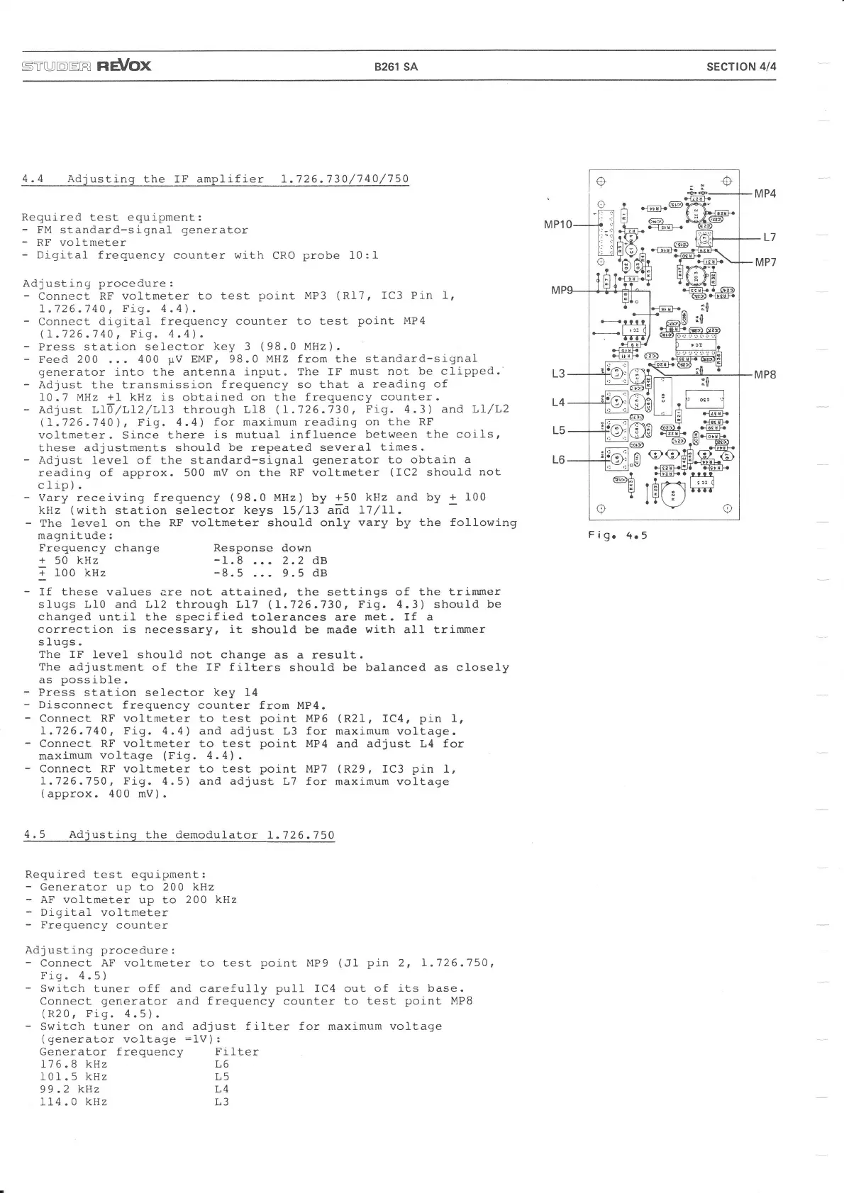
Fig. 4.5) and adjust
L7
for
maximum voltage
(
approx.
400
mV) .
4.5 Adjusting
the
demodulator
1.726.750
Required test equipment:
-
Generator up to 200 kKz
-
AF voltmeter
up to
200 kHz
-
Digital
voltmeter
-
Frequency
counter
Adjusting procedure:
-
Connect AF
voltmeter
to test
point
MP9
(Jl
pin
2, I.726.750,
Frg. 4.5
)
-
Switch tuner off and carefully
pull
IC4 out
of
its
base.
Connect
generator
and
frequency
counter
to test
point
MP8
(R20,
Fig. 4.5).
-
Swi.tch tuner on and adjust
filter for
maximum
voltage
(generator
voltage
=lV)
:
Generator
frequency Filter
176.8
kHz L6
101. 5 kHz L5
99.2
k] z L4
114
.0
kHz L3
Figo
4o5
Response down
-I.8
. ..
2.2 dB
-8.5
... 9.5
dB
ai) . _
($_a.ä-
lr il l-1 b :: 4.:!k
[
,'
L
gRtu\*h@-
r-r-dt!h
:-ilÄp
-
l'p;F
,: .:l l;l( ;) ?
G@1.-J-81-1
_
-VVF
dclh \
ia
rA
aGb a-ffi\-
ir,39H ErT$-T
1 l"t I ö-- a
.
&:i4
t:l
ftf-r
-B..ffi
I--
l+
l0
*.,ilf.--B
:9"
---*#J
@€tr
-#'_
t-:=J
qsF
Ci4.
.$;ffi:i
.E;.l^..{-o.@
"n-E
.t"
I
al;I lr oil -l
l:ll l?l
I
wl
,'
Fl ffi
t:l :
El 6zr)a d..rh
bJ
.@.A.ffi-
eE
.Bf
-
E)
@offirilö
.€q{l:]4 i@-
qE{F.a
rrrt
rßrn-s
k#
vo
 Loading...