sTUDtrR REVOX
8261
SA
sEcTtoN 4/5
ti
-j-l
dvblry
.,1
:1.
ll
{:h
+
-
t
5l
T
'äf
JF"l
€)-
l.loJrul-e s
+ii-;f<
?:RH-ffij:
.1
*J
19
a
foo
.@{
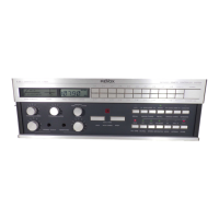
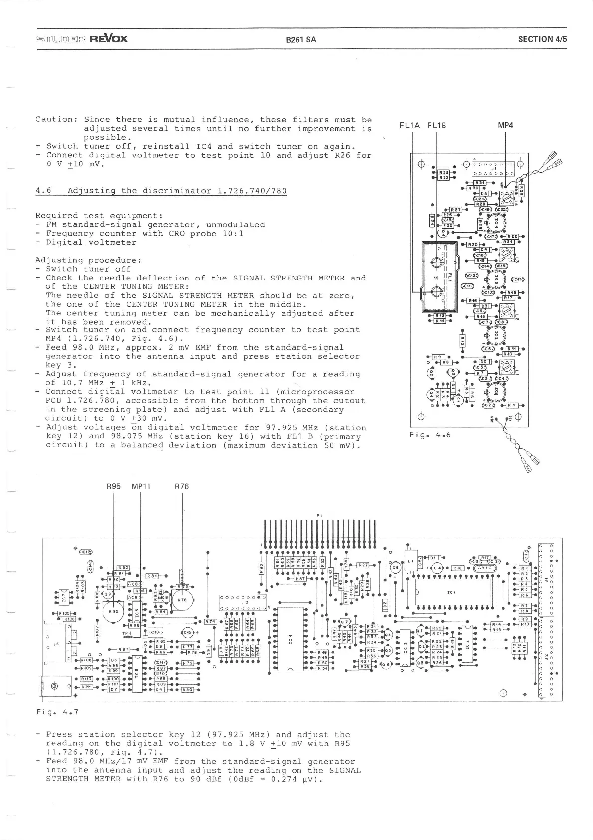
Fig.
4.7
Press
station sei-ector key
12
(97.925
MHz
)
and adjust
the
reading
on the digital
voltmeter to 1.8 V
+10
mV with R95
(L.126.780,
Eig.4.7).
Feed
98.0 MHz/I1
mV
EMF
from
the standard-signal
generator
into
the antenna
input and
adjust the reading on the SIGNAL
STRENGTH
METER with R76
to
90
dBf
(0dBf
=
0.274
yv).
FLlA
FLlB
Caution:
-
Switch
-
Connect
0v+10
Since
there
is
mutual
influence, these filters must be
adjusted several
tj.mes until no
further
improvement is
poss
ible .
tuner off, reinstall
IC4 and switch tuner
on
again.
digital voltmeter
to test
point
10 and adjust R26 for
mV.
4.6 Adjusting
the discriminator
1.726.740l780
Required
test equipment:
-
FM
standard-signal
generator,
unmodul"ated
-
Frequency
counter with
CRO
probe
10: L
-
Digital.
voltmeter
Adjusting
procedure:
-
Switch tuner
off
-
Check
the needle deflection
of the SIGNAL STRENGTH METER and
of the
CENTER TUNING I'IETER:
The
needl,e
of the SIGNAL STRENGTH I'IETER
should be at zero,
the one of
the CENTER
TUNING
METER
in the
mi.ddle.
The
center
tuning meter can be mechanically
adjusted after
it has
been
removed.
-
Switch tuner
on
and connect frequency counter to test
point
MP4
(l-.726.740,
Fig. 4.5).
-
Feed
98.0 MHz, approx. 2 mV EMF from
the
standard-signal
generator
into
the antenna input
and
press
station
selector
key
3.
-
Adjust frequency
of standard-si-gnal
generator
for
a
reading
of 10
.'l
MHz
+
1 kHz.
-
Connect
digiEal
voltmeter to test
point
11
(microprocessor
PCB
1.726.180,
accessible from the bottom through the cutout
in
the screening
plate)
and adjust with
FL1
A
(secondary
circuit)
to 0 V
+30
mV.
-
Adjust
voltages 6n <ij-9itaI
voltmeter
for 97.925
MHz
(station
key
12)
and 98.075
tqlJ'z
(station
key
16) with
FLl
B
(primary
circuit) to
a balanced
deviation
(maximum
deviation
50 mV).
R95 MP1 1
t4l9
i6t
ö
 Loading...