1.2.3
Rear-panel
connectors
[30]
AUDIO
OUTPUT
FIXED
Output
for
connecting an
amplifier on which the
input
sensitivity
can be
matched to the
level
of
the
CD
player (the
REVOX8251
amplifier
is ideally
matched
at the
fac-
tory).
[31]
AUDIO
OUTPUT
VARIABLE Active
speakers or
a
power
amplifier, etc.
can
be connected
directly to this output.
The volume can be
adjusted
with
the
keys
VOLUME
*
and
-
on the front
panel
of the CD
player
t32l
AC
POWER Power inlet
(the
line vol-
tage selector setting can be checked
adjacent to
it).
[33]
REMOTE This connector allows:
a) defeating
the lR receivet and
b)
connecting a cable-type remote
control
device.
1.3 The
compact
disc
1.3.1 lnteresting facts about
the
compact disc
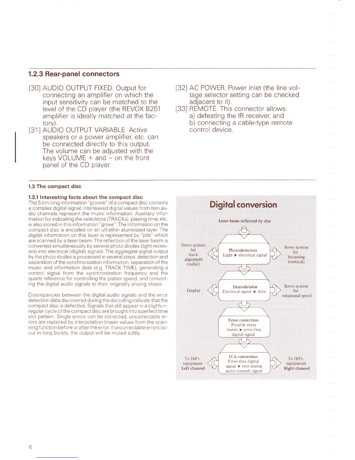
The
5
km long information
"groove"
of a compact disc contains
a complex digital signal:
interleaved digital values from two
au
dio channels
represent
the
music information. Auxiiiary
infor-
mation for indicating the selections
(TRACKs), playing
time.
etc.
is also
stored
in this information
"grove".
The information on the
compact
disc
is encoded on an ultrathin aluminized layer.
The
digital
information
on this
layer is represented
by
"pits"
which
are scanned by a laser beam.
The reflection
of the laser beam
is
converted simultaneously by several
photo
diodes
(light
receiv-
ers)
into
electrical
(digital)
signals The aggregate
signal
output
by the
photo
diodes
is
processed
in
several steps. detection
and
separation of the synchronization
information,
separation of the
music
and information data
(e,9.
TRACK TIME),
generating
a
control
signal
from
the synchronization frequency and
the
quartz
reference for
controlling the
platter
speed,
and convert-
ing
the digital audio signals to their originally analog
shape.
Discrepancies
between the digital audio
signals
and the error
detection
data d
iscovered
du
ring
the decoding indicate that the
compact disc
is
defective. Signals that
still appear
in
a slighly
ir
regular cycle of the compact disc are
brought into a
perfecttime
slot
pattern.
Single errors can be corrected,
uncorrectable
er-
rors
are
replaced
by interpolation
(mean
values
from the scan-
ning f unction
before or after the error. lf uncorrecta
ble errors
oc-
cur in long
bursts. the output will be muted
softly
Pigit6l,
eonvCision
Servo system
foi
track
.
alignment
{radial)
Display
To
HiFi-
equlpment
[.eft channel
Serro syslgm
,lai',
. .iq.quisli'rg
.
,
,(vditical)'
l
Servo system.
-
..for
'
rotational
speed
To
HiFi-
equipment
Right channel
Laser
beam refldcted by,.disc
Photodetectors
Light > electrical signal'
Demodulator
Electrical signal >
data
Error correction
Possible
error
bursts > error-free
digital signal
D/A conversion
Error-free digital
signal >
two analog
audio
(sound)
signal