EasyManua.ls Logo

Rexel CB355E User Manual

Rexel CB355E
55 pages
To Next Page IconTo Next Page
Page #1 background imageLoading...
Page #1 background image
Acco Service Division; Halesowen Industrial Estate, Hereward Rise, Halesowen, West Midlands, B62 8AN
Tel: +44 (0) 845 658 6600 Fax: +44 (0) 8704 215576
Page 1 of 55
ILLUSTRATED PARTS MANUAL:
FLOWLINE COMB & WIRE
BINDER RANGE
FLOWLINE COMB & WIRE
BINDER RANGE
Illustrated Parts Lists &
Service Instructions
CB345E, CB355E, CB405E, WB705E
Compiled by A Bumpsteed Issue No 20
Approved By D Mead Date 25/09/03
Question and Answer IconNeed help?

Do you have a question about the Rexel CB355E and is the answer not in the manual?

Rexel CB355E Specifications

General IconGeneral
BrandRexel
ModelCB355E
CategoryBinding Machine
LanguageEnglish

Summary

Specifications

Preface

Service Instructions

Section 1 – Document Support/Lid

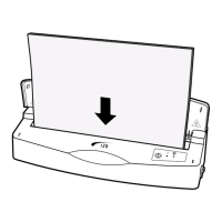
Instructions for removing and replacing the document support lid.

Section 2 – Selector Switches

Procedure for removing and replacing selector switches on specific models.

Section 3 – Top Casing

Steps for removing and replacing the top casing of the binder.

Section 4 – Infill Panel Assemblies

Guidance on removing and replacing infill panel assemblies, including LED PCB.

Section 5 – Comb Opening Mechanism

Instructions for disassembly and assembly of the comb opening mechanism.

Section 6 – Comb Opening Spindle Assembly

Steps for removing and replacing the comb opening spindle assembly.

Section 7 – Lower Casing

Procedures for removing and replacing the lower casing.

Section 8 – Operating Handle / Wire Closing Links

Instructions for handling the operating handle and wire closing links.

Section 9 – Handle Locks

Steps for removing and replacing the handle locking mechanism.

Section 10 – Sideframes/Stub Shaft Assembly

Guidance on disassembling and assembling side frames and stub shafts.

Section 11 – Punches

Procedures for removing and replacing punches for different models.

Section 12 – Punch Selectors

Steps for removing and replacing punch selectors.

Section 13 – Wire Adjuster Mechanism

Instructions for removing and replacing the wire adjuster mechanism.

Section 14 – Gear Box Assembly

Detailed steps for the disassembly and assembly of the gear box.

Wiring Diagrams

Wiring Diagram (230V) – WD431 Issue 1

Electrical wiring diagram for 230V models, Issue 1.

Wiring Diagram (230V) – WD431 Issue 3

Revised electrical wiring diagram for 230V models, Issue 3.

Wiring Diagram (115V) – WD436 Issue 1

Electrical wiring diagram for 115V models, Issue 1.

Amendment Record Sheet

Related product manuals