Do you have a question about the Rexel CB405E and is the answer not in the manual?
Technical specifications for the CB345E model.
Technical specifications for the CB355E model.
Technical specifications for the CB405E model.
Technical specifications for the WB705E model.
Detailed parts list for the CB345E model.
Exploded view and part identification for CB345E.
Detailed parts list for the CB355E model.
Exploded view and part identification for CB355E.
Detailed parts list for the CB405E model.
Exploded view and part identification for CB405E.
Detailed parts list for the WB705E model.
Exploded view and part identification for WB705E.
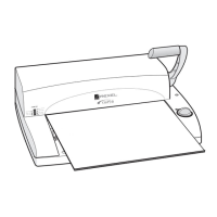
Instructions for removing and replacing the document support lid.
Procedures for selector switch removal and replacement.
Steps for removing and replacing the top casing.
Guide for infill panel assembly removal and replacement.
Instructions for comb opening mechanism removal and replacement.
Procedures for comb opening spindle assembly.
Steps for lower casing removal and replacement.
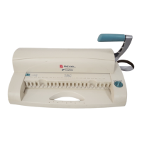
Instructions for operating handle and wire closing links.
Procedures for handle lock removal and replacement.
Steps for sideframes and stub shaft assembly.
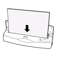
Instructions for punch removal and replacement.
Procedures for punch selector removal and replacement.
Guide for wire adjuster mechanism.
Disassembly and assembly of the gearbox.
Electrical schematic for 230V operation.
Revised electrical schematic for 230V operation.
Electrical schematic for 115V operation.
| Brand | Rexel |
|---|---|
| Model | CB405E |
| Category | Binding Machine |
| Language | English |