Page 2 of 55
ILLUSTRATED PARTS MANUAL:
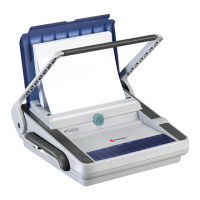
FLOWLINE COMB & WIRE
BINDER RANGE
TABLE OF CONTENTS
ILLUSTRATED PARTS MANUAL
FLOWLINE RANGE
Page
Contents 2
Preface 3 - 4
Illustrations and Parts with 5 - 20
Recommended Spares
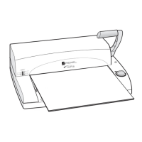
CB345E 5 - 7
CB345E Diagram 8
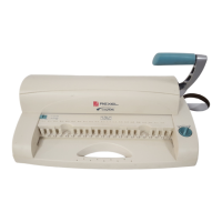
CB355 E 9 - 11
CB355E Diagram 12
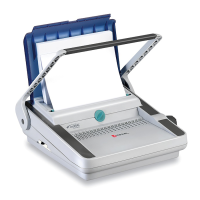
CB405E 13 - 16
CB405E Diagram 17
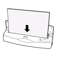
WB705E 18 - 20
WB705E Diagram 21
Service Instructions 22 - 46
Section 1 Document Support Lid 22
Section 2 Selector Switches 23
Section 3 Top Casing 24
Section 4 Infill Panel Assemblies 25
Section 5 Comb Opening Mechanism 26
Section 6 Comb Opening Spindle Assemble 27
Section 7 Lower Casing 28
Section 8 Operating Handle/Wire Closing Links 29
Section 9 Handle Locks 30
Section 10 Side frames/Stub Shaft Assembly 31
Section 11 Punches 32
Section 12 Punch Selector 33
Section 13 Wire Adjuster Assembly 34
Section 14 Gear Box Assembly 35 - 46
Wiring Diagrams 47 – 49
Wiring Diagram (230V) – WD431 Issue 1 47
Wiring Diagram (230V) – WD431 Issue 3 48
Wiring Diagram (115V) – WD436 Issue 1 49