12-2 Connection System Synchronous Motors MKD
19.05.2004 Version7.0 DOK-MOTOR*-MKD*******-PR07-EN-P
12.2 Motors with connector box
Connection diagram
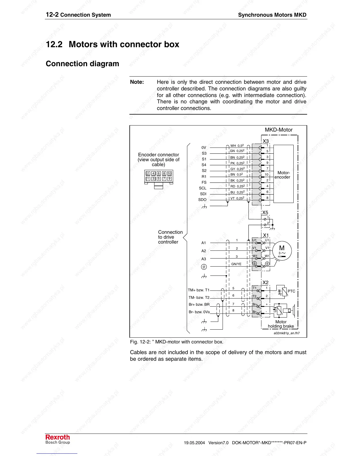
Note: Here is only the direct connection between motor and drive
controller described. The connection diagrams are also guilty
for all other connections (e.g. with intermediate connection).
There is no change with coordinating the motor and drive
controller connections.
U1
V1
W1
A1
A2
A3
M
3
Motor
holding brake
TM- bzw. T2
PTC
U
U1
V1
W1
MKD-Motor
Motor-
encoder
T1
T2
Br+
Br-
X2
X1
X3
1
2
3
GN/YE
5
6
7
8
1
2
+
-
TM+ bzw. T1
Br- bzw. 0V
B
Br+ bzw. BR
VT 0,25
2
BU 0,25
2
RD 0,25
2
BK 0,25
2
GY 0,25
2
PK 0,25
2
BN 0,25
2
GN 0,25
2
WH 0,5
2
BN 0,5
2
1
5
3
9
7
10
2
4
6
8
0V
S3
S1
S4
S2
R1
FS
SCL
SDI
SDO
Connection
to drive
controller
Encoder connector
(view output side of
cable)
a02mk81p_en.fh7
1
2
X5
13579
246810
Fig. 12-2: ” MKD-motor with connector box.
Cables are not included in the scope of delivery of the motors and must
be ordered as separate items.