Form 433-CV/LN, Page 12
is in operation and on standby. Incorrect inlet pressure could cause
excessive manifold gas pressure immediately or at some future time. If
natural gas supply pressure is too high, install a regulator in the supply
line before it reaches the heater. If natural gas supply pressure is too
low, contact your gas supplier.
Instructions on How to Check Manifold Pressure
(can only be done after heater is installed):
1) With the manual valve positioned to prevent flow to the main burn-
ers, connect a manometer to the 1/8" pipe outlet pressure tap in the
valve. NOTE: A manometer (fluid-filled gauge) is recommended rather
than a spring type gauge due to the difficulty of maintaining calibra-
tion of a spring type gauge.
2) Open the valve and operate the heater. Measure the gas pressure to
the manifold. Normally adjustments should not be necessary to the
factory preset regulator.
If adjustment is necessary, set pressure to correct settings by turning
the regulator screw IN (clockwise) to increase pressure. Turn regulator
screw OUT (counterclockwise) to decrease pressure.
Derating by Manifold Pressure Adjustment for
High Altitude Operation
If the heater is being installed between 2000 and 5000 ft (610 to 1525M)
and it was determined in Paragraph 4 that derating by manifold pres-
sure adjustment is permissible, follow the instructions below.
Instructions for Derating a Heater by Adjusting Manifold
Pressure
1. Determine the required manifold pressure for the elevation where
the heater will be operating. If unsure of the elevation, contact the
local gas supplier.
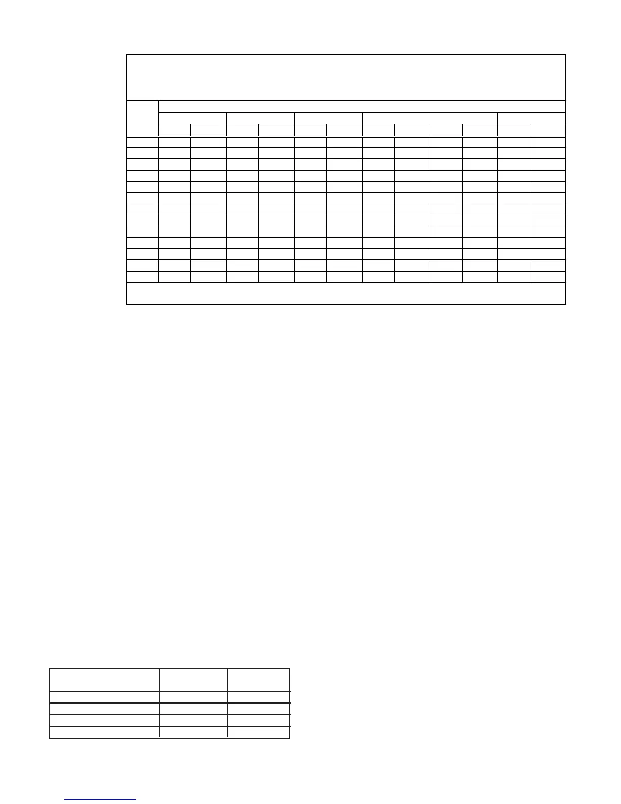
Manifold Pressure Settings by Elevation
Altitude Natural Gas Propane Gas
Feet Meters (inches W.C.) (inches W.C.)
0- 2000 1-610 3.5 10.0
2001-3000 911-915 2.8 7.7
3001-4000 916-1220 2.5 7.1
4001-5000 1221-1525 2.3 6.4
2. With the manual valve positioned to prevent flow to the main burn-
ers, connect a manometer to the 1/8” pipe outlet pressure tap in the
Sizing a Gas
Supply Line
Capacity of Piping
Cubic Feet per Hour based on 0.3" w.c. Pressure Drop
Specific Gravity for Natural Gas -- 0.6 (Natural Gas -- 1000 BTU/Cubic Ft)
Specific Gravity for Propane Gas -- 1.6 (Propane Gas -- 2550 BTU/Cubic Ft)
Length Diameter of Pipe
of 1/2" 3/4" 1" 1-1/4" 1-1/2" 2"
Pipe Natural Propane Natural Propane Natural Propane Natural Propane Natural Propane Natural Propane
20' 92 56 190 116 350 214 730 445 1100 671 2100 1281
30' 73 45 152 93 285 174 590 360 890 543 1650 1007
40' 63 38 130 79 245 149 500 305 760 464 1450 885
50' 56 34 115 70 215 131 440 268 670 409 1270 775
60' 50 31 105 64 195 119 400 244 610 372 1105 674
70' 46 28 96 59 180 110 370 226 560 342 1050 641
80' 43 26 90 55 170 104 350 214 530 323 990 604
90' 40 24 84 51 160 98 320 195 490 299 930 567
100' 38 23 79 48 150 92 305 186 460 281 870 531
125' 34 21 72 44 130 79 275 168 410 250 780 476
150' 31 19 64 39 120 73 250 153 380 232 710 433
175' 28 17 59 36 110 67 225 137 350 214 650 397
200' 26 16 55 34 100 61 210 128 320 195 610 372
Note: When sizing supply lines, consider possibilities of future expansion and increased requirements.
Refer to National Fuel Gas Code for additional information on line sizing.
valve. Use a fluid-filled manometer that is readable to the nearest
tenth of an inch w.c.
3. Remove the cap from the pressure adjusting screw and adjust the
manifold pressure to the pressure setting selected from the table.
Cycle the main burners once or twice to properly seat the adjust-
ment spring in the valve.
Re-check the pressure. If necessary, re-adjust the pressure. When
the pressure is correct, remove the manometer and replace the cap.
Check for leaks at the pressure tap fitting.
4. With the heater operating, determine that the inlet pressure to the
heater for natural gas is between 5 and 14 inches w.c. and for pro-
pane between 10 and 14 inches w.c. Take this reading as close as
possible to the heater. (Most heaters are now equipped with gas
valves that have an inlet pressure tap.) If the inlet pressure is not
within the specified range, the inlet pressure must be corrected
and Steps 3 and 4 repeated.
5. Find the Manifold Pressure Adjustment label in the plastic bag that
contained these instructions. Using a permanent marker, fill-in the
pressure setting. Adhere the label on the heater near the gas valve
so that it is conspicuous to someone servicing the valve and/or heater.
13. Electrical Supply and
Connections
All electrical wiring and connections, including electrical grounding
MUST be made in accordance with the National Electric Code ANSI/
NFPA No. 70 (latest edition) or, in Canada, the Canadian Electrical
Code, Part I-C.S.A. Standard C22.1. In addition, the installer should
be aware of any local ordinances or gas company requirements that
might apply.
Check the rating plate on the heater for the supply voltage and current
requirements. A dedicated line voltage supply with fused disconnect
switch should be run directly from the main electrical panel to the heater.
All external wiring must be within approved conduit and have a mini-
mum temperature rise of 60°C
.
Conduit from the disconnect switch
must be run so as not to interfere with the service panels of the heater.
The electrical supply and control wiring enter at the rear of the heater
and connect to the integrated circuit board. The 115 volt supply wiring
connects to pigtails on the lower portion of the circuit board. The ter-
minal strip for 24 volt thermostat connections is located on the upper
portion of the circuit board. See Figure 7.
12. Gas Piping and Pressures (cont'd)
Manifold or Orifice Pressure Settings (cont'd)
 Loading...