0108MLOOGBEN
14
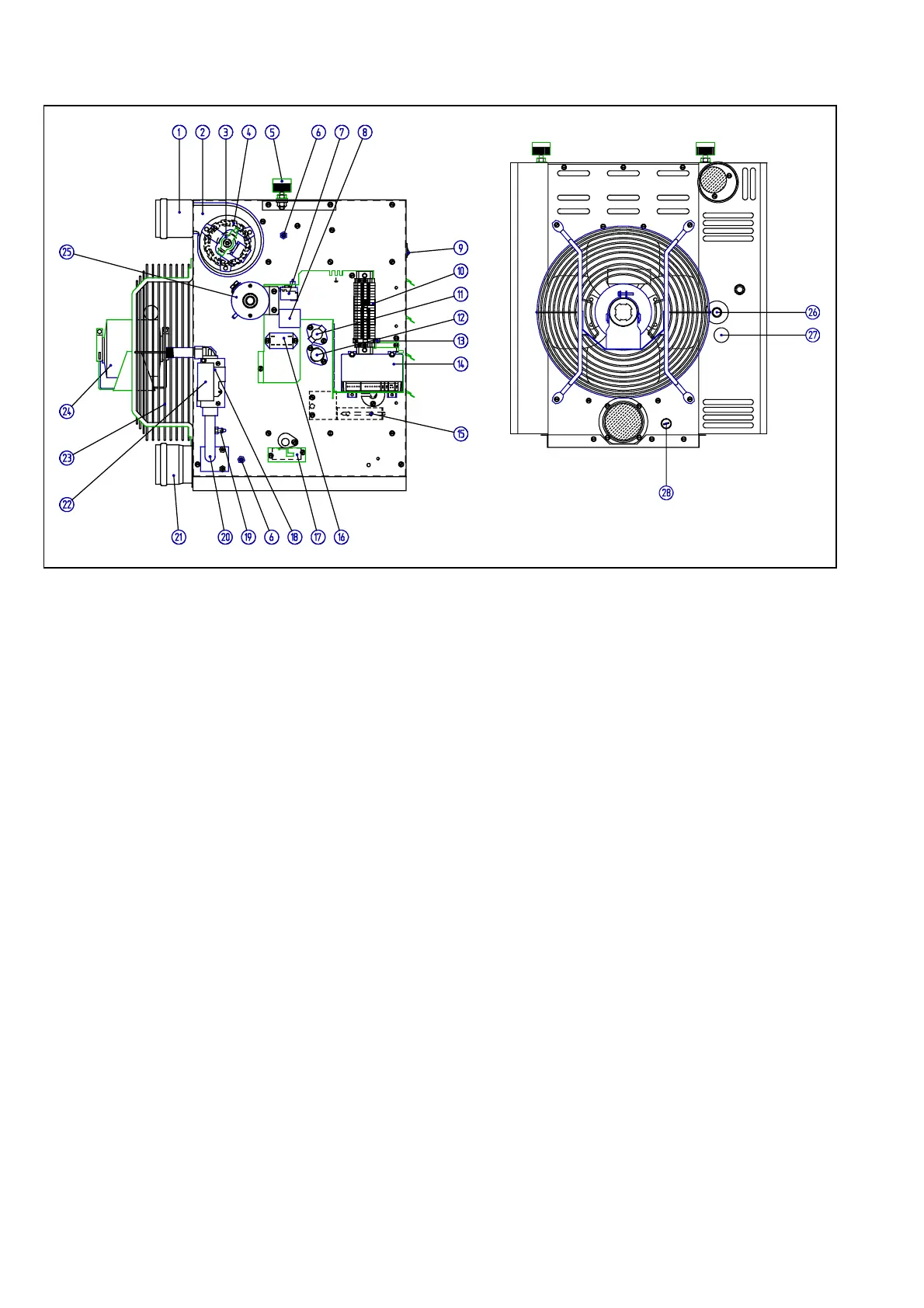
Figure 10 COMPONENT PARTS LOCATION
Legend figure 10:
1. Flue outlet
2. Venter housing
3. Venter motor
4. Fan impeller
5. Suspension socket 1" BSP
6. Combustion circuit reference pressure points
7. Thermal overheat control and reset switch LC3
8. Isolation transformer (not GB)
9. Burner lock-out reset switch
10. Wiring terminals
11. Thermal limit control LC1
12. Thermal fan control FCR
13. Fuse in terminal assembly
14. Automatic burner control
15. Capillary for LC3
16. Relay for isolation transformer (not GB)
17. Igniter assembly
18. Multi-functional gas control
19. Burner pressure test point
20. Burner manifold
21. Combustion air inlet socket
22. Gas control solenoids
23. Air circulation fan
24. Air circulation fan motor
25. Combustion air proving differential switch
26. Inlet gas connection Rc ½
27. Burner gas pressure adjustment access
28. Test point for combustion air temperature
END OF SERVICE INSTRUCTIONS
 Loading...


