24
I-RX-RG-RPV (09-19) PN1027501R0
INSTALLATION—CONTINUED
Electrical Supply and Connections—Continued
Disconnect Switch
• A disconnect switch is a required part or this installation. Switches are available as options or parts or may be
purchased locally. When ordered as an optional component, the disconnect switch is shipped separately.
• The disconnect switch may be fusible or non-fusible. When providing or replacing fuses in a fusible disconnect
switch, use dual element time delay fuses and size to 1.25 times the maximum total input amps listed on the unit
rating plate.
• When installing, take care to ensure that the conduit and switch housing are clear of furnace panels and inspection
plates. Allow at least 4 feet of service room between the switch and the removable panels.
Control Thermostat
⚠ CAUTION ⚠
Ensure that the thermostat has an adequate VA rating for the total requirements. Add the coil rating
of all relays and match the thermostat rating.
• A thermostat is not standard equipment but is an installation requirement. Use either an optional thermostat available
with the heater or a field-supplied thermostat. Install in accordance with the thermostat manufacturer’s instructions.
• A 24V thermostat must be used to actuate low-voltage gas controls. If line voltage from the thermostat to the unit
is desired, consult the Factory Representative.
• Wiring between the thermostat and the heater must be suitable for a temperature rise of 140°F (60°C). Labeled
thermostat leads are provided in the heater junction box for connecting thermostat wiring.
• Thermostats should be located 5 feet above the floor on an inside wall, not in the path of warm or cold air currents
and not in corners where air may be pocketed. Do NOT install on cold air walls. For specific connection details,
refer to instructions provided with the thermostat.
• If more than one unit is cycled from one thermostat, separately-activated relays must be substituted at unit
thermostat connections.
• Low-voltage (24V) thermostats are equipped with heat anticipators that level out unit cycling for optimum temperature
control. Set the heat anticipator at full load control amps.
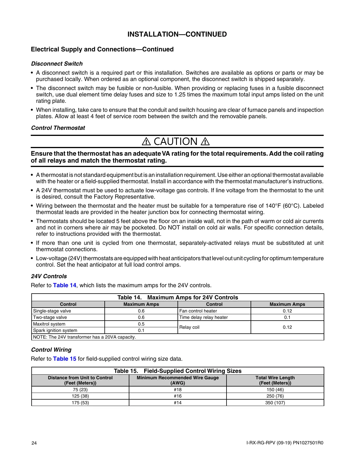
24V Controls
Refer to Table 14, which lists the maximum amps for the 24V controls.
Table 14. Maximum Amps for 24V Controls
Control Maximum Amps Control Maximum Amps
Single-stage valve 0.6 Fan control heater 0.12
Two-stage valve 0.6 Time delay relay heater 0.1
Maxitrol system 0.5
Relay coil 0.12
Spark ignition system 0.1
NOTE: The 24V transformer has a 20VA capacity.
Control Wiring
Refer to Table 15 for field-supplied control wiring size data.
Table 15. Field-Supplied Control Wiring Sizes
Distance from Unit to Control
(Feet (Meters))
Minimum Recommended Wire Gauge
(AWG)
Total Wire Length
(Feet (Meters))
75 (23) #18 150 (46)
125 (38) #16 250 (76)
175 (53) #14 350 (107)
 Loading...