9
I-RX-RG-RPV (09-19) PN1027501R0
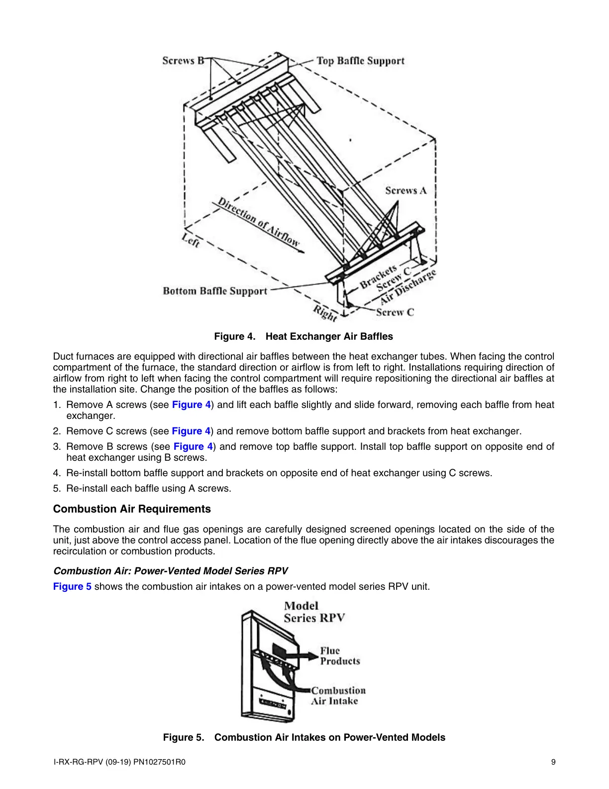
Figure 4. Heat Exchanger Air Baffles
Duct furnaces are equipped with directional air baffles between the heat exchanger tubes. When facing the control
compartment of the furnace, the standard direction or airflow is from left to right. Installations requiring direction of
airflow from right to left when facing the control compartment will require repositioning the directional air baffles at
the installation site. Change the position of the baffles as follows:
1. Remove A screws (see Figure 4) and lift each baffle slightly and slide forward, removing each baffle from heat
exchanger.
2. Remove C screws (see Figure 4) and remove bottom baffle support and brackets from heat exchanger.
3. Remove B screws (see Figure 4) and remove top baffle support. Install top baffle support on opposite end of
heat exchanger using B screws.
4. Re-install bottom baffle support and brackets on opposite end of heat exchanger using C screws.
5. Re-install each baffle using A screws.
Combustion Air Requirements
The combustion air and flue gas openings are carefully designed screened openings located on the side of the
unit, just above the control access panel. Location of the flue opening directly above the air intakes discourages the
recirculation or combustion products.
Combustion Air: Power-Vented Model Series RPV
Figure 5 shows the combustion air intakes on a power-vented model series RPV unit.
Figure 5. Combustion Air Intakes on Power-Vented Models
 Loading...