22
I-SCE (09-18) PN207697R9
GAS PIPING AND PRESSURES—CONTINUED
Pressure Testing Gas Supply Piping—Continued
• All piping must be in accordance with requirements outlined in the National Fuel Gas Code ANSI/Z223.1 (latest
edition) or CSA B149.1 and B149.2 (refer to Installation Codes). Gas supply piping installation should conform
with good practice and with local codes.
• These separated-combustion units for natural gas are orificed for gas having a heating value of 1000 (±50) BTUh
per cubic foot. If the gas at the installation does not meet this specification, consult the factory for proper orificing.
• Pipe joint compounds (pipe dope) shall be resistant to the action of liquefied petroleum gas or any other chemical
constituents of the gas being supplied.
Gas Connections
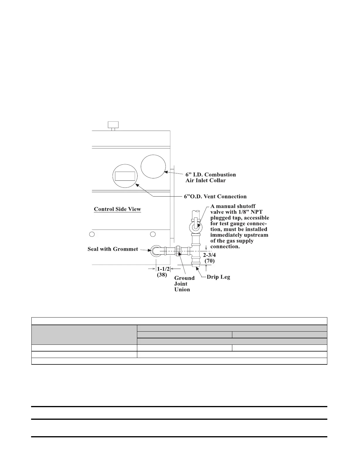
Gas connections are shown in Figure 20.
Figure 20. Gas Connections
Gas connections sizes are listed in Table 10.
Table 10. Gas Connection Sizes
Gas Type
Model
125–250 300–400
Connection Size (Inches)
Natural Gas 1/2 3/4
Propane Gas 1/2
NOTE: The above are not supply line sizes. They are gas connection sizes for a standard unit.
• Seal the opening for the gas supply pipe with the grommet provided (see Figure 20).
• Install a ground joint union and manual shutoff valve upstream of the unit control system. The 1/8-inch plugged
tapping in the shutoff valve provides connection for the supply line pressure test gauge. The National Fuel Gas
Code requires the installation of a trap with a minimum 3-inch drip leg. Local codes may require a longer drip leg,
typically 6-inch (see Figure 20).
⚠ DANGER ⚠
All components of a gas supply system must be leak tested prior to placing the equipment in service. NEVER TEST
FOR LEAKS WITH AN OPEN FLAME.
 Loading...