2
OPT-CL31-CL32 (11-21) 102247-A
GENERAL INFORMATION—CONTINUED
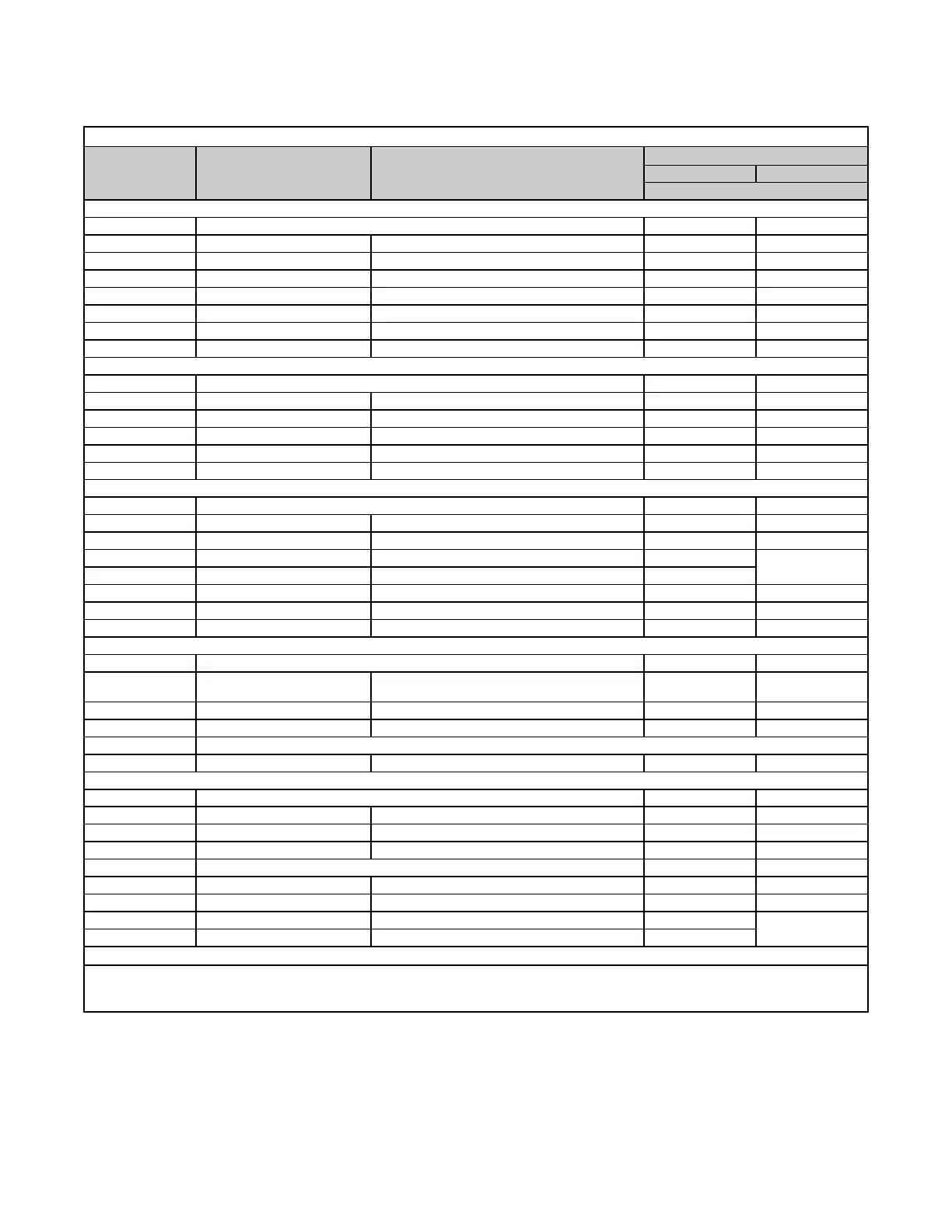
Table 2. Relay Kit Components
Item No.*
Component Description
Option**
CL31 CL32
PN (Quantity)
APD, UDAP, UDAS, UDX, UDZ, UEAS, and UEZ Models
— Option package PN 197155 (1) 197156 (1)
1 Relay assembly Includes relay and specially-designed bracket 197157 (2) 197157 (1)
1A Relay Wired and mounted on bracket 18549 (2) 18549 (1)
2 Screw Self-drilling, for securing relay bracket 195249 (2) 195249 (1)
3 Cable clamp 3/16 16228 (2) 16228 (1)
4 Label Wiring diagram 197164 (2) 197164 (1)
5 Transformer 40VA 194808 (1) —
6 Wiring harness assembly Brown wires 197160 (1) —
UDBP, UDBS, UBX, and UBZ Models
— Option package PN 202958 (2) 197156 (1)
1 Relay assembly Includes relay and specially-designed bracket 197157 (2) 197157 (1)
1A Relay Wired and mounted on bracket 18549 (2) 18549 (1)
2 Screw Self-drilling, for securing relay bracket 195249 (2) 195249 (1)
3 Cable clamp 3/16 16228 (2) 16228 (1)
4 Label Wiring diagram 197164 (2) 197164 (1)
F and B Models
— Option package PN 102248 (1) 102249 (1)
1 Relay assembly Includes relay and specially-designed bracket 102243 (2) 102243 (1)
1A Relay Wired and mounted on bracket 18549 (2) 18549 (1)
2 Screw Sheet metal, #6 × 1-1/2, for transformer 103152 (2)
—
2A Tinnerman clip #C1110-62, for transformer screws 111233 (2)
3 Cable clamp 3/16 16228 (2) 16228 (1)
4 Label Wiring diagram 131127 (2) 131127 (1)
5 Transformer 35VA 102708 (1) —
LDAP Models
— Option package PN 208366 (1) 208367 (1)
1 Relay assembly
Includes relay, 42-inch red and white wires, and
6-inch blue and brown wires
208365 (2) 208365 (1)
1A Relay With wires and wire terminals 18549 (2) 18549 (1)
2 Screw #8-18 × 1/2, for securing relay bracket 38529 (2) 38529 (2)
3 Not used
4 Label Wiring diagram 208185 (2) 208185 (1)
VR Models
— Option package PN 205685 (1) 205686 (1)
1 Relay assembly Includes relay and specially-designed bracket 102243 (2) 102243 (1)
1A Relay Wired and mounted on bracket 18549 (2) 18549 (1)
2 Screw #8 × 1 121033 (4) 121033 (2)
2A Spacer 98872 (4) 98872 (2)
3 Cable clamp 3/16 16228 (2) 16228 (1)
4 Label Wiring diagram 197164 (2) 197164 (1)
5 Transformer 40VA 194808 (1)
—
5A Wire connector Twist-on, orange 16354 (1)
*See Figure 1 and Figure 2.
**Option CL31 includes components for one control unit and one additional unit. Option CL32 includes components for each additional non-
control unit with the following exception: for 208V, 230V, or 460V F, B, and VR models, option CL32 is used for the for the control unit and
each additional non-control unit (refer to Table 1).