5
OPT-CL31-CL32 (11-21) 102247-A
b. For models F and B:
(1) At rear of heater, remove thermostat terminal strip screws and remove terminal strip.
(2) Slide relay assembly (1 and 1A) bracket underneath thermostat terminal strip and secure bracket, terminal
strip, and cable clamp (3) as shown using existing screws
(3) Secure blue and brown wires in cable clamp (3).
c. For model LAPD:
(1) Remove access panel from main heat section.
(2) Position relay assembly (1 and 1A) on control panel and secure using screws (2) from kit.
d. For model VR:
(1) At end of burner/control box, remove thermostat terminal strip screws and remove terminal strip.
(2) Secure terminal strip, relay assembly (1 and 1A), and cable clamp (3) as shown using screws (2) and
spacers (2A).
(3) Secure blue and brown wires in cable clamp (3).
⚠ CAUTION ⚠
Be careful not to short thermostat leads to a metal surface. Doing so will cause the transformer
to fail and require replacement.
NOTE: VR models do not have a W2 terminal. Splice between the DSI control COM and 24V on the
transformer and use the twist-on wire connector (5A) to connect the wires.
4. Connect relay (1A) to TEW-type control wiring in accordance with model-specific wiring diagram label
(4) from kit. Do not exceed length and distance listed in Table 3.
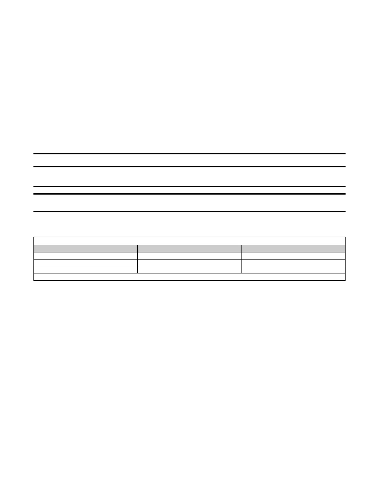
Table 3. Control Wiring Specifications
Gauge
Maximum Length (Feet (Meters))*
Maximum Distance (Feet (Meters))
12 2100 (640) 1050 (320)
14 1300 (457) 650 (198)
18 500 (152) 250 (76)
*For complete circuit.
5. Install wiring diagram label:
a. For future reference, check appropriate box for heater function—PRIMARY HEATER for control unit or
SECONDARY HEATER for non-control unit—on wiring diagram label (4).
b. Locate required wiring diagram label position on unit:
(1) For models APD, APD, UBX, UBZ, UDAP, UDAS, UDBP, UDBS, UDX, UDZ, UEAS, and UEZ, label location
is bottom rear corner of access panel.
(2) For models F and B, label location is lower right corner of outer left (when facing rear of heater) side panel.
(3) For model LDAP, label location is inside of access panel.
(4) For model VR, label location is rear of burner box above terminal strip.
c. Wipe surface with clean, dry cloth.
d. Remove label backing and adhere label to unit.
6. Restore system to service:
a. Turn ON gas and electric power.
b. Light heater in accordance with lighting instructions.
c. Check for proper operation.
 Loading...