Do you have a question about the Reznor XL30 and is the answer not in the manual?
Details the specific furnace models compatible with the power venter kit.
Highlights critical safety warnings, cautions, and dangers associated with the power venter installation.
Lists the voltage options available for the power vent kits.
Provides guidance on selecting the correct power vent kit based on furnace model and size.
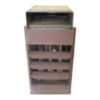
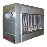
Details the components, dimensions, and specifications of the venter assembly.
Explains the venter's control system and the function of the venter adapter.
Describes the fundamental operation and sequencing of the power venter.
Details the steps for installing the flue adapter and the venter assembly onto the furnace.
Explains how to connect the electrical wiring for the power venter system according to diagrams.
Outlines specific requirements for vent pipe type, length, diameter, and termination.
Illustrates vertical and horizontal vent terminal configurations and required clearances.
Describes the procedure to test the vent system for safe and proper operation after installation.
Lists part numbers and descriptions for replacement venter assembly components.
This document describes the installation and maintenance of the Reznor Power Vent Kit for duct furnaces, specifically for models X, DX, HX, CX, HCX, XE, HXE, CXE, and HCXE. This kit is an optional motorized vent exhauster designed to facilitate the installation of gravity-vented heaters in areas with negative pressure (up to 0.15 IN WC) or where horizontal venting is required.
The power vent kit's primary function is to assist in the safe and efficient venting of combustion gases from the furnace to the outside atmosphere. It includes a venter assembly, a venter flue adapter, and a control system. The venter assembly consists of a corrosion-resistant steel housing with a baked enamel finish, enclosing a centrifugal blower with forward-curved blades and a motor. The control system incorporates a pressure switch to initiate and terminate burner operation and a thermal switch for post-purge functionality, preventing lockouts due to temperature-sensitive blocked vent systems. Low-voltage control is managed by a built-in relay.
The operational sequence begins when the thermostat calls for heat, closing the circuit to the venter's relay coil. After a 15-60 second delay, the venter starts, and the air from its blower closes the pressure switch. This action completes the electrical circuit to the burner controls, opening the gas valve. When the thermostat is satisfied, the gas valve closes. The thermal switch then allows the venter blower to continue operating for a post-purge period, and finally, the pressure switch opens when the venter blower stops.
Voltage Options: The power vent kits are available in four voltage options:
Venter Assembly Blower Specifications:
Venting Requirements:
The power vent kit allows for greater flexibility in furnace installation by enabling horizontal venting and operation in negative pressure environments. It is designed for specific Reznor models (X/DX/HX, CX/HCX, XE/HXE, CXE/HCXE, XL/CXL, XLB/CXLB). The venter adapter ensures proper dilution air flow for safe and efficient operation. The kit includes all necessary components for installation, though some field-supplied items like sheet metal screws, vent pipe elbow (for vertical flue), wiring (18 GA for control, 14 GA for line voltage), and wiring accessories (flexible conduit, connectors) are required.
The venter assembly can be positioned with its discharge outlet pointing horizontally to vertically, but never below horizontal. This ensures proper exhaust and prevents spillage. The system is designed to comply with national and local electrical and gas codes, including ANSI/NFPA No. 70, Canadian Electrical Code Part I-C.S.A. Standard C22.1, and National Fuel Gas Code Z223.1 or CAN/CGA B149.1 and B149.2.
The document emphasizes the importance of proper installation by a qualified agency to prevent property damage, injury, or death. Regular operational testing is required after installation to ensure proper venting. This involves turning on gas and electric, lighting the unit according to instructions, and checking the flow direction at the drafthood's relief opening (room air should flow into the opening).
The manual provides a detailed list of replacement parts for currently-manufactured venter assemblies, including the cover, switches (sail/pressure), thermal switch, relay, blower housing, wheel, junction box, plate, fan blade, mounting bracket, motor, capacitor, and tubing. It notes that obsolete venter assemblies with a "V" prefix (line voltage controls) have replacement parts similar to low-voltage models. Obsolete 200, 300, and 400 series venters are not available and require replacement of the complete venter with a correct currently-manufactured model.
The document highlights that the venter assembly is factory-assembled and wired, including the blower, motor, capacitor, pressure switch, thermal switch, and junction box. This simplifies initial setup. Wiring diagrams are provided for different control systems (line voltage controls, spark pilot, match-lit pilot with pressure switch) to guide electrical connections. The importance of maintaining the vent system in a structurally-sound and properly-operating condition is stressed to ensure safe operation and prevent incomplete combustion and carbon monoxide production.