Form O-Y P/N 273647R5, Page 25
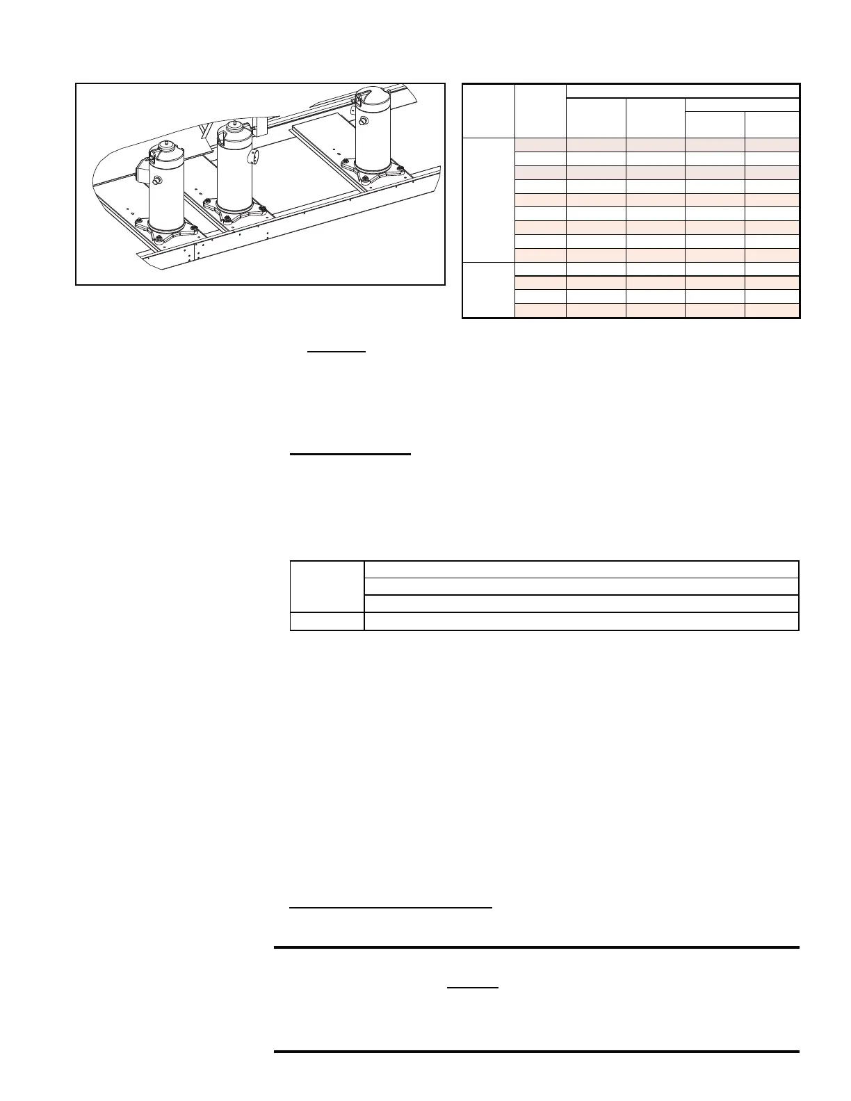
Approximate R-410A Refrigerant Charge (lbs) for by Size and Compressor for Each Circuit
Model Size
R-410A Charge (lbs) by Compressor Circuit
AB
DH (Reheat)
Low
Enthalpy
High
Enthalpy
YDHA
and
YDMA
060 15 -- 5 5
090 15 -- 5 5
120 8 8 5 5
150 8 8 5 5
180 15 15 5 5
210 15 15 5 5
240 15 15 5 5
300 19 19 6 8
360 19 19 6 8
YDSA
120 10 10 5 5
150 10 10 5 5
180 14 14 6 8
210 14 14 6 8
B
Opt
DH
A
Step 10. System Startup
Assure voltage to compressor does not drop below minimum allowable voltage
(e.g. 187 volts for 230/208-3-60, 415 volts for 460/3/60, 518 volts for 575/3/60)
during the period the compressor is trying to start. If a low voltage or voltage
imbalance condition exists, the electrical problem must be determined and
corrected prior to operating the unit.
Voltage Imbalance9ROWDJHLPEDODQFHLVEHFRPLQJDPRUHFRPPRQSUREOHP
In a 3-phase system, excessive voltage imbalance between phases will cause
motors to overheat and compressors to fail. Maximum allowable imbalance is
7RGHWHUPLQHYROWDJHLPEDODQFHPHDVXUHDQGUHFRUGWKHYROWDJHRIDOOWKUHH
phases. Take the measurements at the compressor terminals with the compressor
operating.
Voltage Imbalance Formula:
Key:
999 OLQHYROWDJHVDVPHDVXUHG
9$$YHUDJH 999
9' /LQH9ROWDJH99RU9WKDWGHYLDWHVIDUWKHVWIURPDYHUDJH9$
Formula:
RI9ROWDJH,PEDODQFH >9$9'@9$
,IWKHLPEDODQFHLVZLWKLQWKHWROHUDQFHYROWDJHLPEDODQFHLVQRWDSUREOHPDQG
WKHV\VWHPPD\EHRSHUDWHG,IWKHLPEDODQFHH[FHHGVWKHWROHUDQFHIROORZ
the procedures below.
Solutions to Voltage Imbalance:
The cause for a voltage imbalance problem can originate at the power company or
can be caused inside the building. Try the following on-site solution to determine if
the problem can be easily resolved.
5ROOWKHFRQQHFWLRQVDWWKHFRPSUHVVRUWHUPLQDOVRQHIRUZDUG&RQQHFWWKHZLUH
now on Terminal 1 to Terminal 2, 2 to 3, and 3 to 1. Re-measure and re-calculate
WKHYROWDJHLPEDODQFH,IWKHLPEDODQFHLVZLWKLQWKHV\VWHPPD\EHRSHUDWHG
If the imbalance is not within tolerance, roll the connections one more forward.
Re-measure and re-calculate the voltage imbalance. If the imbalance is within
WKHV\VWHPPD\EHRSHUDWHG,IWKHYROWDJHLPEDODQFHVWLOOH[FHHGVGR
QRWVWDUWWKHV\VWHP&RQWDFWWKHEXLOGLQJRZQHURUSHUVRQUHVSRQVLEOHWRKDYHDQ
electrician analyze the buildings's power supply and load distribution.
Power Supply Voltage Phasing&RQQHFWUHIULJHUDQWSUHVVXUHJDXJHVWRWKH
suction and discharge lines of the compressors and an electric meter to the power
supply.
CAUTION: Be sure to connect pressure gauges to the suction
and discharge lines before system startup so that compressor
rotation can be checked immediately. Scroll compressors will be
destroyed if allowed to operate in the wrong direction. See Hazard
Levels, page 2.
FIGURE 18 - Compressors
,GHQWL¿HGE\&LUFXLW