Form O-Y P/N 273647R5, Page 27
&$87,21$IWHUFOHDQXSLVFRPSOHWHUHPRYHWKHVXFWLRQOLQH¿OWHU
drier. See Hazard Levels, page 2.
d) 9HULI\VXEFRROLQJDQGVXSHUKHDWUHIHUWRStep 11).
e) When the system is operating properly, remove the gauges.
Or, IF the oil measured in Step 2ZDVQRWVLJQL¿FDQWO\OHVVWKDQWKDW
shown in the table on page 20 or the acid test in Step 2 did not indi-
cate a compressor burnout, continue to the review in Step 13.
Step 13 . Review ALL Steps to ensure that nothing was overlooked.
All systems have a unit-mounted, 24-volt programmable controller. The controller
is factory programmed to match the control selection on the order (Option D19 for
space temperature control or Option D21 for makeup air control). See the appropriate
FRQWUROLQVWUXFWLRQPDQXDO)RUP&3<'RU&3<'IRUPRUHGHWDLOV
Some sensors are standard and others will depend on option selection.
Service: If a sensor needs to be replaced, use only a factory authorized replacement
part designed for the purpose.
If a controller needs to be replaced, it must be replaced with the same controller and
VRIWZDUH&RQWDFW\RXUGLVWULEXWRURUWKHIDFWRU\VHUYLFHGHSDUWPHQWIRUGHWDLOV
3.8 Other Controls
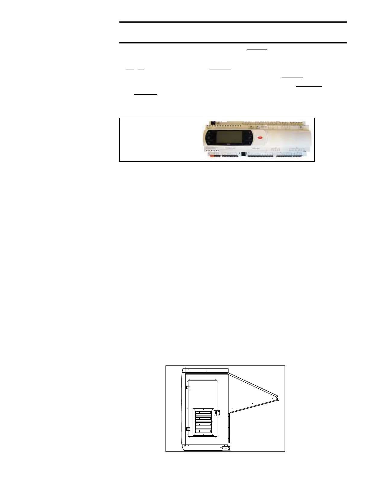
3.8.1 Programmable Digital Controller and Sensors
System
Programmable
Controller with
Integral Display
3.8.2 Voltage
Protection,
Option PL4
Function: Phase loss and low or high voltage can cause damage to electrical com-
ponents. This safety control monitors phase loss and voltage and shuts down the unit
when its limits are exceeded. The device is auto reset and allows the unit to restart
when the power conditions are corrected.
4.1 Power Exhaust, Option PE
,IHTXLSSHGZLWKRSWLRQDOSRZHUH[KDXVWWKHUHLVDQ(&0IDQLQWKHH[KDXVWDLUVWUHDP
and gravity dampers in the opening on the corner of the "access" side of the system.
The power exhaust fan operation is from a constant volume, in response to a building
pressure sensor, or by an adjustable offset to the supply fan. Adjustments and set-
tings are through the system controller.
Service: 3RZHUH[KDXVWIDQPRWRULVSHUPDQHQWO\OXEULFDWHGOXEULFDWLRQLVQRW
required, During maintenance, remove any accumulation of dirt and grease from the
IDQDQGGDPSHUV7KHH[KDXVWIDQ&)0ZDVFKHFNHGDQGEDODQFHGDWVWDUWXS7R
recheck, follow the instructions in the installation manual, Form I-Y, Paragraph 10.3.
The system may be equipped with either an integral power exhaust or an energy
recovery wheel with an attached power exhaust module.
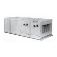
Optional Power
Exhaust Damper
is in the door
allowing access
to the power
exhaust fan.
FIGURE 19 - Exhaust
Damper Location
for either gravity or
power exhaust
4.0 Maintenance/Service Procedures - Power Exhaust and Energy Recovery