Form O-Y, PN 273647R5, Page 40
Vent Maintenance
Remove dirt and grease from the venter motor housing. The venter motor is perma-
QHQWO\OXEULFDWHGGRQRWOXEULFDWH&DUHIXOO\FOHDQWKHYHQWHUZKHHODVVHPEO\EHLQJ
cautious not to bend the wheel.
&KHFNWKHYHQWDWOHDVWRQFHD\HDU&OHDQWKHWHUPLQDOVFUHHQ,IHTXLSSHGZLWK
optional vertical vent extension, inspection should include all joints, seams, and the
terminal. Replace any defective parts.
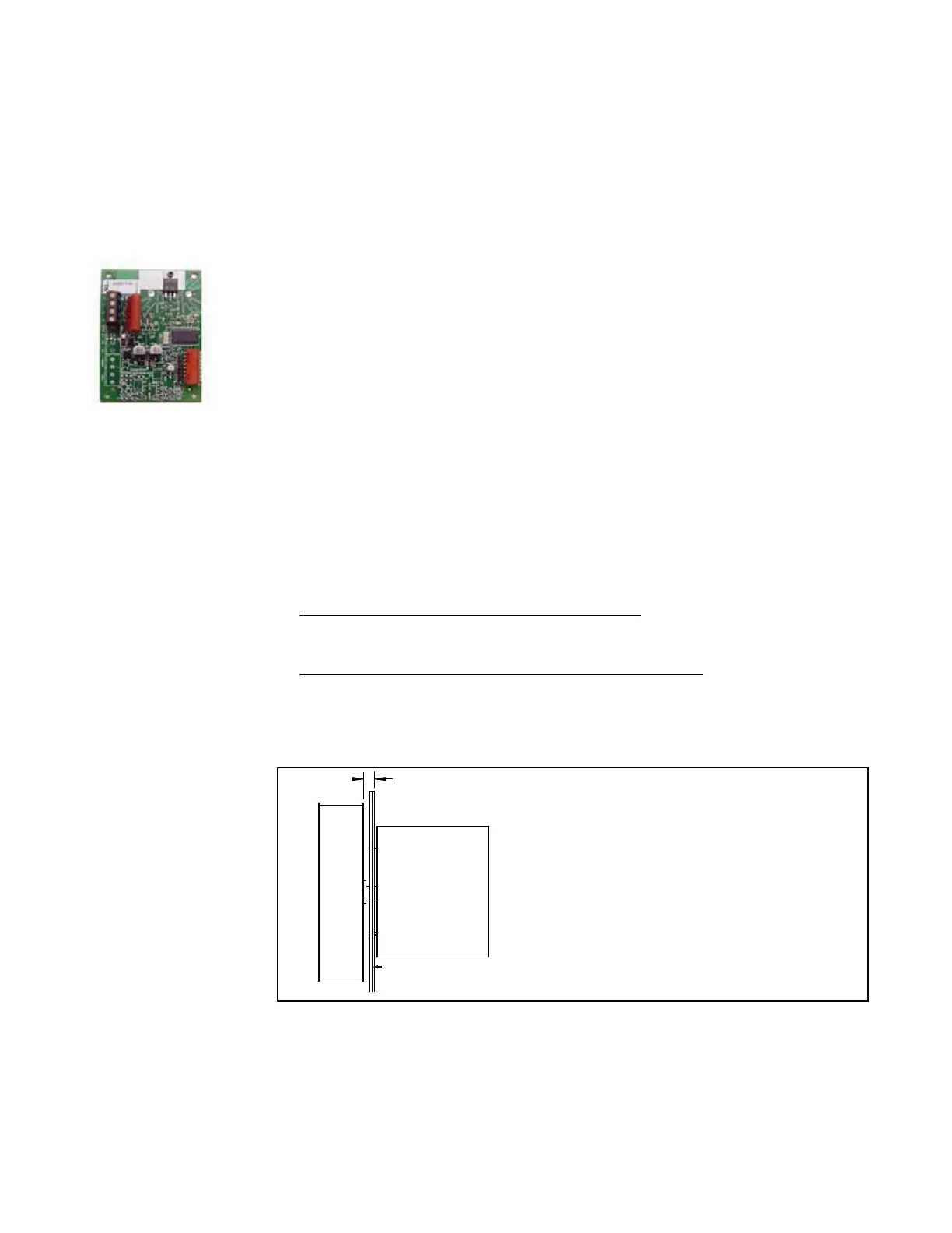
Venter Speed Board Options AG73 and AG74 - Modulating gas controls have a
proprietary electronically controlled venter system that provides the required volume
RIFRPEXVWLRQDLUDQGFRUUHFWJDVSUHVVXUHWRPDLQWDLQWKHUPDOHI¿FLHQF\GXULQJ
SHULRGVRIPRGXODWLRQ&KDQJHRIYHQWHUVSHHGLVFRQWUROOHGE\DQHOHFWURQLFERDUG
located on the heat section control panel (See FIGURE 23, page 32). The venter sys-
tem always operates at high speed during pre-purge and post-purge periods. Speed
selection occurs after there is a call for burner ignition.
Venter Speed Board
5.3 Vent
Maintenance
and Operation
Maintenance
Instructions for the
Venter Motor and
Wheel
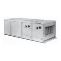
FIGURE 28 - Venter
Wheel Position on
the Shaft (High
(I¿FLHQF\0RGHOV
Remove dirt and grease from the motor casing, the venter housing, pressure sensing
WDSDQGWKHYHQWHUZKHHO9HQWHUPRWRUEHDULQJVDUHSHUPDQHQWO\OXEULFDWHG
Follow these instructions for replacement of the venter motor and wheel assembly.
Keep all hardware removed to be used in re-assembling and installing the replace-
ment parts.
1. Turn off the gas and disconnect the electric power.
2. Open the burner/control compartment door panel.
3. Disconnect the two or three venter motor wires at the DSI control or the venter
speed control board, capacitor wires at the capacitor (if applicable), and ground
screw (located on the control panel).
4. 2QKLJKHI¿FLHQF\FRQGHQVLQJKHDWVHFWLRQ, holding the venter motor,
remove the screws that attach the venter motor mounting plate to the venter
housing. Remove the motor and wheel assembly from the heater.
2QVWDQGDUGHI¿FLHQF\QRQFRQGHQVLQJKHDWVHFWLRQ, remove the venter
KRXVLQJDVVHPEO\E\UHPRYLQJWKHVFUHZVWKDWDWWDFKLWWRWKHÀXHZUDSSHU
5. Re-assemble with the replacement venter motor and wheel assembly. See
FIGURE 28 shown below for correct spacing. If there is a motor plate gasket,
check it. If the gasket is damaged, replace it.
6. Follow the wiring diagram to connect the venter wires.
7.&ORVHWKHGRRUSDQHO5HVWRUHSRZHUWRWKHKHDWHUDQGWXUQRQWKHJDV/LJKW
IROORZLQJWKHLQVWUXFWLRQVRQWKHOLJKWLQJLQVWUXFWLRQSODWH&KHFNIRUSURSHU
operation.
NOTES:
1) Manufacturer recommends replacing
venter motor capacitor when replacing venter
motor.
2QVWDQGDUGHI¿FLHQF\QRQ
condensing heat section, venter motor and
wheel assembly cannot be disassembled.
Motor plate to wheel
G150, G225, G300, G302
G372, G452, G525, G602
Venter
Motor
Venter Wheel
Motor Plate (and Motor
Plate Gasket, P/N 221163)
.31"
5.0 Maintenance/Service Procedures - Gas Heat Section (cont'd)