Form O-Y P/N 273647R5, Page 47
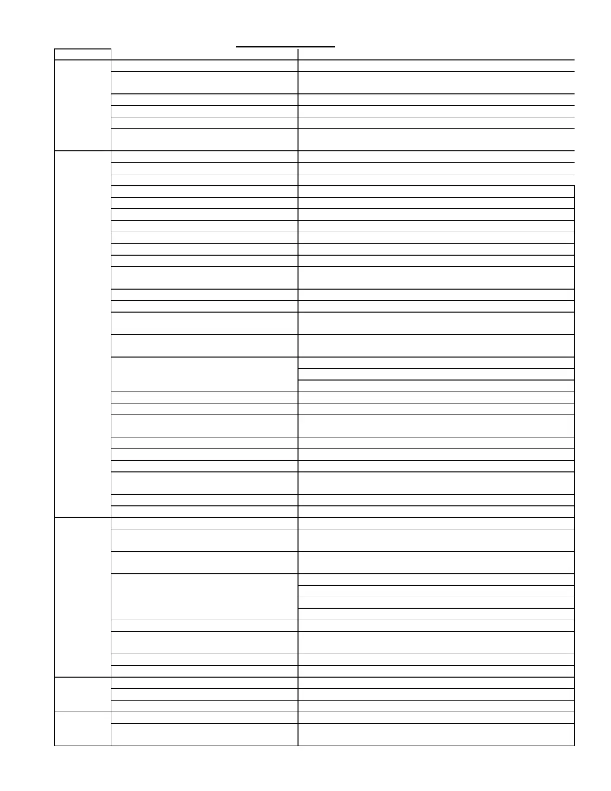
7.3.2 General Troubleshooting - Gas Heat Section - (Option G__ or H__)
PROBLEM PROBABLE CAUSE REMEDY
9HQWHUPRWRU
will not start
1. No power to unit. 7XUQRQSRZHUFKHFNVXSSO\IXVHVRUPDLQFLUFXLWEUHDNHU
2. No 24 volt power to ignition system circuit
board.
7XUQXSWKHUPRVWDWFKHFNFRQWUROWUDQVIRUPHURXWSXW
3. Integrated circuit board fuse blown. &RUUHFWFDXVHUHSODFHIXVH
4. No power to venter motor. 4. Tighten connections at circuit board and/or motor terminals.
5. Integrated circuit board defective. 5. Replace integrated circuit board.
6. Defective venter motor or capacitor 6. Replace defective parts. Recommend replacing capacitor when
replacing motor. See Paragraph 5.2.
Burner will
not light
1. Manual valve not open. 1. Open manual valve.
2. Air in the gas line. 2. Bleed gas line (initial startup only).
3. Gas pressure too high or too low. 3. See installation manual, Form Y, Paragraph 9.2.1.
4. No Spark: 4.
D/RRVHZLUHFRQQHFWLRQV a) Be certain all wire connections are solid.
b) Transformer failure. b) Be sure 24 volts is available.
c) Incorrect spark gap. c) Maintain spark gap at 1/8".
d) Spark cable shorted to ground. d) Replace worn or grounded spark cable.
e) Spark electrode shorted to ground. e) Replace if ceramic spark electrode is cracked or grounded.
f) Ignition system circuit board not grounded. f) Make certain circuit board is grounded to furnace chassis.
g) Unit not properly grounded. J0DNHFHUWDLQXQLWLVSURSHUO\¿HOGJURXQGHGWRHDUWKJURXQGDQG
SURSHUO\SKDVHG/WRKRWOHDG/WRQHXWUDO
h) Ignition system circuit board fuse blown. K&RUUHFWFDXVHUHSODFHIXVH
i) Modulation system out of acceptance range L5HYLHZHUURUFRGHVRQERDUGUHIHUWRSDJH
j) Faulty circuit board. j) If 24 volt is available to the circuit board and all other causes have
been eliminated, replace board.
/RFNRXWGHYLFHLQWHUUXSWLQJFRQWUROFLUFXLW
by above causes.
5. Reset lockout by interrupting control.
&RPEXVWLRQDLUSURYLQJVZLWFKQRWFORVLQJ &OHDQYHQWHUZKHHO
a) Remove obstructions from vent.
b) Replace faulty tubing to pressure switch.
7. Faulty combustion air proving switch. 7. Replace combustion air proving switch.
9DOYHQRWRSHUDWLQJ 8.
a) Defective valve. a) If 24 volt is measured at the valve connections and valve remains
closed, replace valve.
E/RRVHZLUHFRQQHFWLRQV E&KHFNDQGWLJKWHQDOOZLULQJFRQQHFWLRQV
&LUFXLWERDUGGRHVQRWSRZHUYDOYHV 9.
D/RRVHZLUHFRQQHFWLRQV D&KHFNDQGWLJKWHQDOOZLULQJFRQQHFWLRQV
b) Flame sensor grounded. E%HFHUWDLQÀDPHVHQVRUOHDGLVQRWJURXQGHGRULQVXODWLRQRU
ceramic is not cracked. Replace as required.
c) Incorrect gas pressure. c) See installation manual, Form I-Y, Paragraph 9.2.1.
G&UDFNHGFHUDPLFDWVHQVRU d) Replace sensor.
Burner
cycles on
and off
1. Gas pressure too high or too low. 1. See installation manual, Form I-Y, Paragraph 9.2.1.
&LUFXLWERDUGQRWJURXQGHG 2. Make certain integrated circuit board is grounded to furnace
chassis.
3. Faulty integrated circuit board 3. If 24 volt is available to the circuit board and all other causes have
been eliminated, replace board.
&RPEXVWLRQDLUSURYLQJVZLWFKQRWFORVLQJ &OHDQYHQWHUZKHHO
a) Make sure unit is properly vented.
b) Remove obstructions from vent.
c) Replace faulty tubing to pressure switch.
5. Faulty combustion air proving switch. 5. Replace combustion air proving switch.
6. Flame sensor grounded. %HFHUWDLQÀDPHVHQVRUOHDGLVQRWJURXQGHGRULQVXODWLRQRU
ceramic is not cracked. Replace as required.
&UDFNHGFHUDPLFDWVHQVRU 7. Replace sensor.
8. Incorrect polarity. 8. Reverse line volt leads to integrated circuit board.
9HQWHUPRWRU
will not run
&LUFXLWRSHQ &KHFNZLULQJDQGFRQQHFWLRQV
2. Defective integrated circuit board. 2. Replace board.
3. Defective motor. 3. Replace motor.
9HQWHUPRWRU
cuts out on
overload
/RZRUKLJKYROWDJHVXSSO\ &RUUHFWHOHFWULFVXSSO\
2. Defective motor or capacitor. 2. Replace defective parts. Recommend replacing capacitor when
replacing motor. See Paragraph 5.2
 Loading...