Form O-Y, PN 273647R5, Page 8
3.2 Supply Fan
and Variable
Frequency Drive
Fan motors are permanently lubricated; lubrication is not required, During
maintenance, remove any accumulation of dirt and grease7KHIDQ&)0ZDV
checked and balanced at startup. To recheck, follow the instructions in the installation
manual, Form I-Y, Paragraph 10.3.
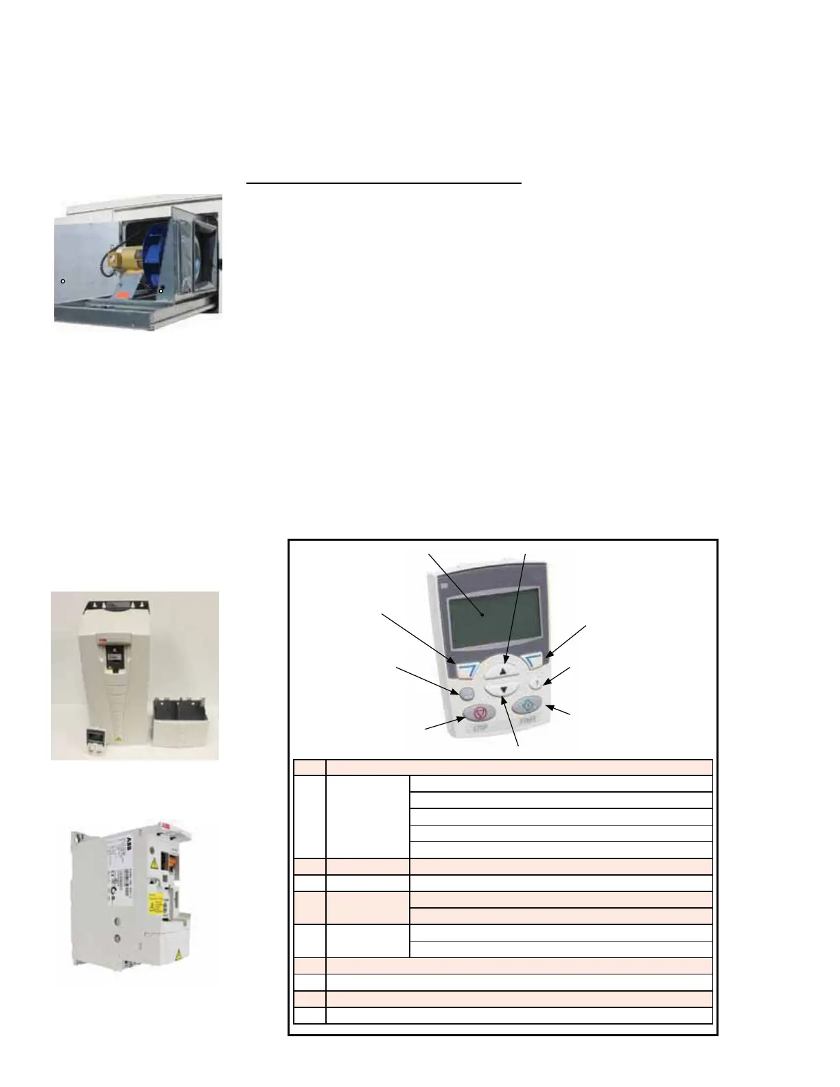
If service is required, the supply fan is mounted on a sled that will slide out of the
cabinet.
Instructions for sliding out the supply fan:
1. Turn off the power and lock the disconnect switch.
2. Open the supply fan door and the cooling cabinet door.
3. 7KHÀH[LEOHGXFWMRLQLQJWKHVXSSO\IDQWRWKHFRROLQJFRPSDUWPHQWLVYLVLEOH
/RFDWHWKHPHWDOÀDQJHKROGLQJWKHGXFWWRWKHFDELQHW5HPRYHWKHWZRVFUHZV
IURPIDQVOHGORFDWLRQVVKRZQLQSLFWXUHRQWKHOHIWDQGWKHÀDQJHWRIUHHWKHGXFW
so that it can be slid out with the fan.
4. Open the electrical box on the fan. Mark and disconnect the wires.
5. &DUHIXOO\VOLGHWKHFRPSOHWHIDQVOHGRXWRIWKHFDELQHW
6. When service is complete, slide the sled into the cabinet. Re-connect the wires
DQGUHDWWDFKWKHÀDQJHWRKROGWKHÀH[LEOHGXFWLQSODFH,IWKHSUHVVXUHWXEHZDV
removed during service, be sure to re-attach it securely. Reinstall two screws into
the fan sled.
Variable Frequency
Drive
Approx fan sled
screw locations
Function: When the main controller calls for supply fan operation, a variable fre-
TXHQF\GULYH9)'UHVSRQGVWRRSHUDWHWKHPRWRU
7KH9)'LVORFDWHGRQWKHKLJKYROWDJHHOHFWULFDOSDQHO6HHFIGURE 1, page 4).
&RQWURORIWKHYDULDEOHIUHTXHQF\GULYHPRGXOHLVGLFWDWHGE\WKHPDLQFRQWUROOHUDQG
GHSHQGLQJRQZKDWZDVRUGHUHGFDQIXQFWLRQLQUHVSRQVHWRWHPSHUDWXUH&2
2
, or
pressure controls. !
Service: Remove any dirt or dust. Check the wire connections. ,ID9)'QHHGV
to be replaced, use a factory-authorized replacement designed for the application.
Supply fan in "slide
out" position
Code Control Panel Display
1 /&'GLVSOD\
Divided into 5
areas
8SSHUOHIW&RQWUROORFDWLRQ
Upper right - unit of the displayed value
&HQWHU3DUDPHWHUVDQGVLJQDOYDOXHVPHQXVDQGDODUPFRGHV
/RZHUOHIWDQGFHQWHU2SHUDWLRQVWDWH
/RZHUULJKW0RWRUURWDWLRQ
2 RESET / EXIT Resets faults and exits to higher menus
3 MENU / ENTER Menu selection and saves value
4 UP Scrolls up through menu / list
Increases value of parameters or reference values
5 DOWN Scrolls down through menu / list
Decreases value of parameters or reference values
6 /2&5(09)'FRQWUROOHGE\PDLQFRQWUROOHU
7 ',5&KDQJHVWKHGLUHFWLRQRIWKHPRWRU
8 STOP - Stops the drive
9 START - Starts the drive
9) START
7) DIR
3) MENU / ENTER
5) DOWN
4) UP
8) STOP
6) LOC / REM
2) RESET / EXIT
1) LCD Display
Variable Frequency
Drive Model ACS355
Variable Frequency
Drive Model ACS550
FIGURE 4 - VFD
Display
3.0 Maintenance and Service Procedures - Unit & Cooling Components (cont'd)