TRAP Remote Controls
DS-TRAP-10 Page 3
Installation
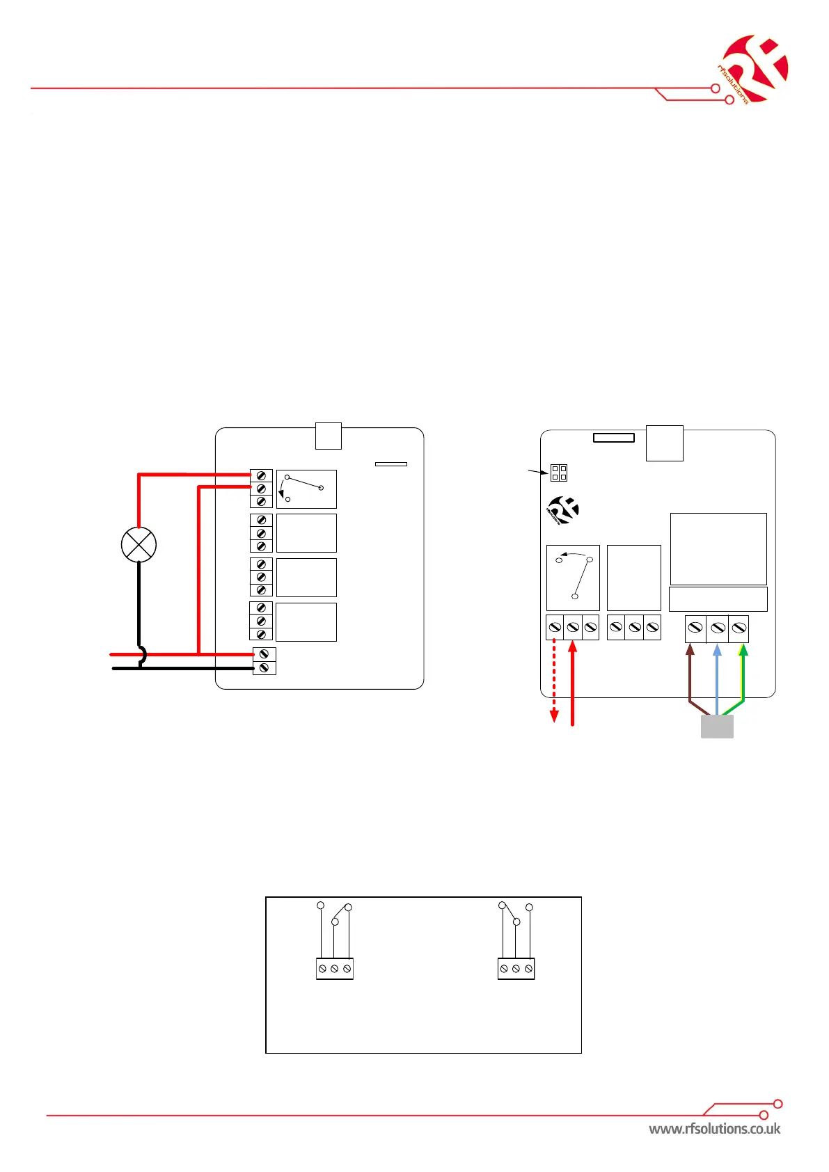
Below is a simple example showing one possible way to wire a relay in order to give switched power
to an external load:
When the relay is energised the ‘COM’ connects to ’NO’ and power is applied to the Load.
1. Open the enclosure by removing fixing screws from the enclosure
2. Remove the antenna and slide out the circuit board.
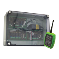
3. Connect the power supply screw terminals 12-32V ac or dc to the supply terminals.
4. Wire your desired connections to the relay switches
5. Once all required wiring is complete, use the handheld transmitter to switch the outputs.
6. Change the output functions to latching, / Momentary Operation.
12-30V Version 230Vac Version
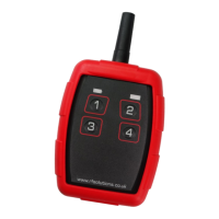
Receiver Operation - Relay Outputs
The TRAP system provides changeover relay switches each capable of switching up to 1.2KW
(5A @ 230V). Each relay is independent and separately controlled. Each output relay provides
an isolated switch. Connections are Common (COM), Normally Open (NO) and Normally Closed
(NC).