EasyManua.ls Logo

RF-Star RF-BM-BG22A3 - Functional Block Diagram; Part Number Conventions; Figure 1. Functional Block Diagram of RF-BM-BG22 A3(I); Figure 2. Part Number Conventions of RF-BM-BG22 A3(I)

RF-Star RF-BM-BG22A3
27 pages
Print Icon
To Next Page IconTo Next Page
To Previous Page IconTo Previous Page
Loading...
RF-BM-BG22A3(I)
www.szrfstar.com V1.3 - Aug., 2022
Shenzhen RF-star Technology Co., Ltd. Page 3 of 26
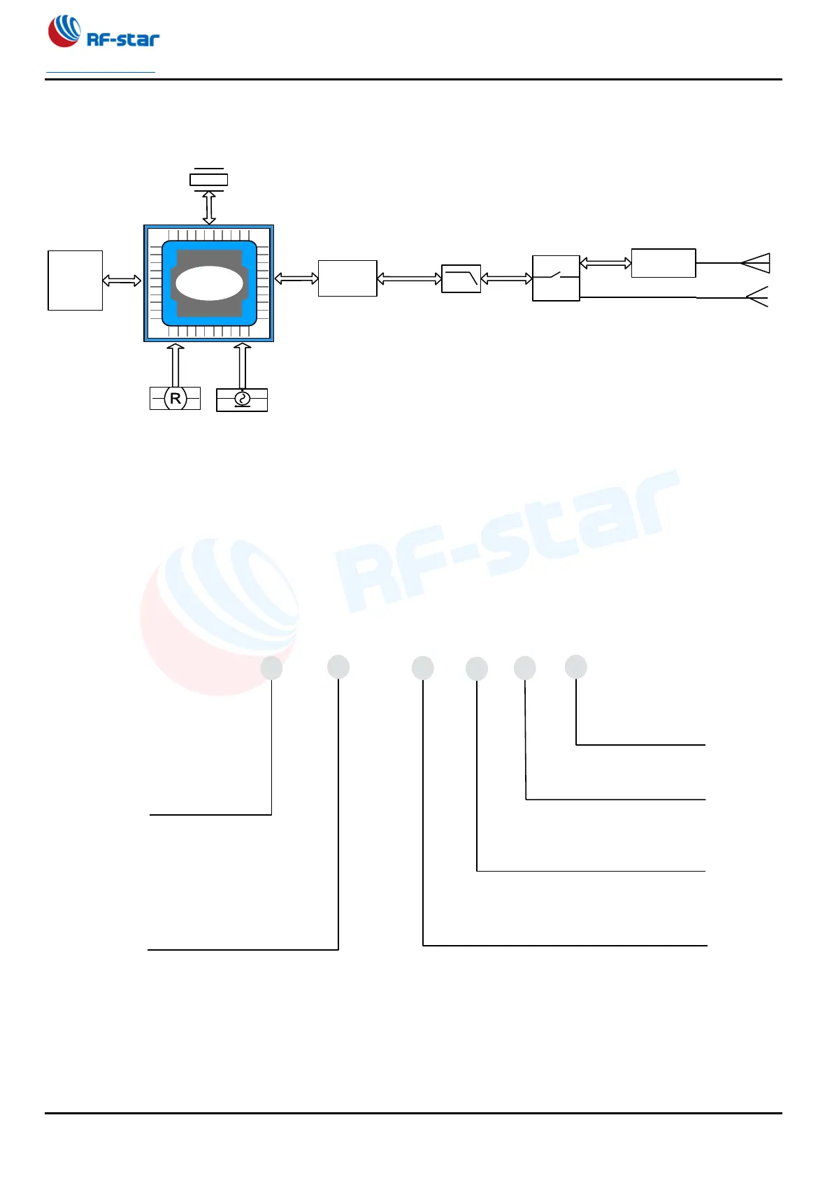
1.5 Functional Block Diagram
Figure 1. Functional Block Diagram of RF-BM-BG22A3(I)
1.6 Part Number Conventions
The part numbers are of the form of RF-BM-BG22A3(I) where the fields are defined as follows:
Figure 2. Part Number Conventions of RF-BM-BG22A3(I)
GPIOs
Debug
Reset
Low-Pass
Filter
Power Supply
DC-DC mode: 2.2 V to 3.8 V
Bypass mode: 1.8 V to 3.8 V
Antenna
Matching
38.4 MHz
Matching
Half-Hole
ANT Pin
PCB Antenna /
IPEX Connetor
Antenna
Switch
RF
BM
BG22
Company Name
RF-STAR
Wireless Type
Bluetooth Module
Chipset
EFR32BG22 Series
-
-
A
Module Version
The A HW Version
3
IC Code
EFR32BG22C224
I
Antenna Type
I: IPEX Connector

Table of Contents

Other manuals for RF-Star RF-BM-BG22A3

Related product manuals