EasyManua.ls Logo

RF-Star RF-BM-BG22A3 - Module Pin Diagram; Pin Functions

RF-Star RF-BM-BG22A3
27 pages
Print Icon
To Next Page IconTo Next Page
To Previous Page IconTo Previous Page
Loading...
RF-BM-BG22A3(I)
www.szrfstar.com V1.3 - Aug., 2022
Shenzhen RF-star Technology Co., Ltd. Page 8 of 26
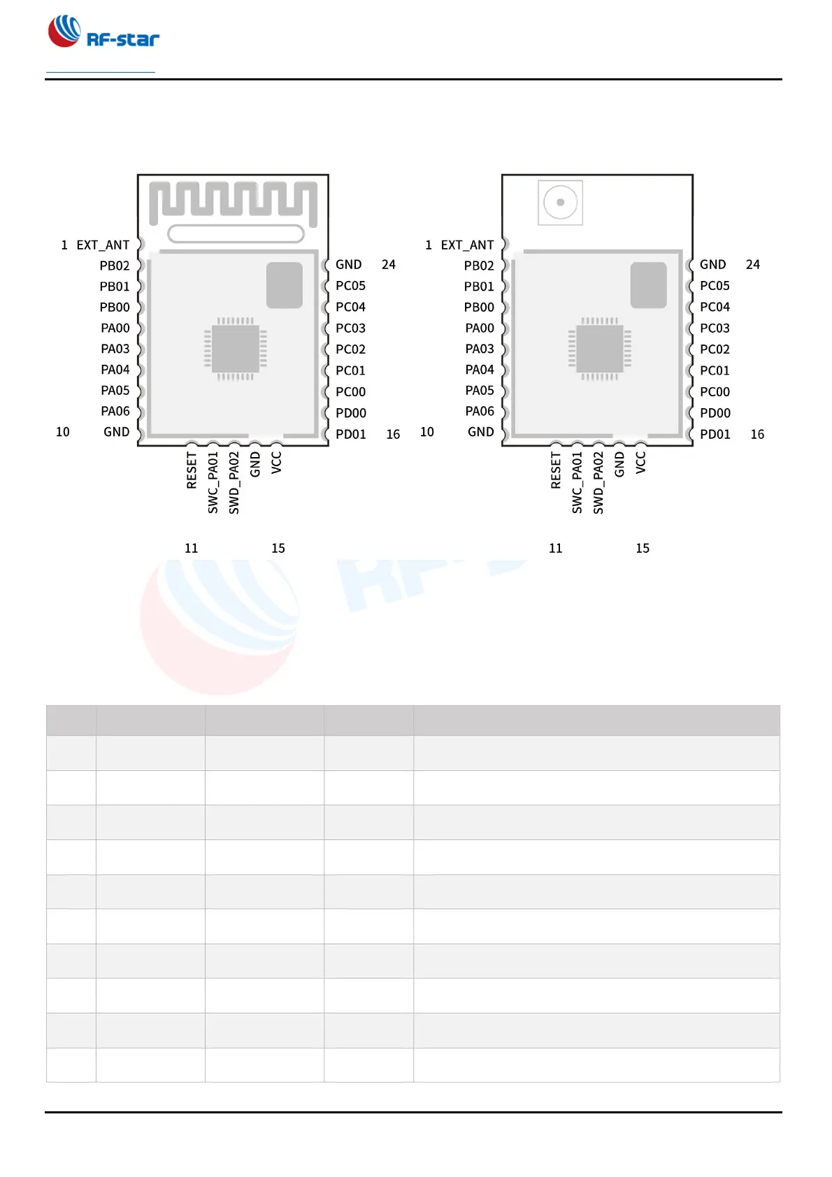
2.2 Module Pin Diagram
RF-BM-BG22A1 RF-BM-BG22A1I
Figure 3. Pin Diagram of RF-BM-BG22A3(I)
2.3 Pin Functions
Table 3. Pin Functions of RF-BM-BG22A3(I)
Pin
Name
Chip Pin
Pin Type
Description
1
EXT_ANT
-
-
External antenna pin.
2
PB02
PB02
I/O
GPIO
3
PB01
PB01
I/O
GPIO
4
PB00
PB00
I/O
GPIO
5
PA00
PA00
-
GPIO
6
PA03
PA03
I/O
GPIO
7
PA04
PA04
I/O
GPIO
8
PA05
PA05
I/O
GPIO
9
PA06
PA06
I/O
GPIO
10
GND
GND
-
Ground

Table of Contents

Other manuals for RF-Star RF-BM-BG22A3

Related product manuals