Do you have a question about the Rheem 80MDV SERIES and is the answer not in the manual?
Follow instructions to prevent fire or explosion, property damage, injury, or death.
Instructions are for qualified service personnel only. Failure to follow can cause injury or death.
Product contains chemicals known to cause cancer or reproductive harm.
Steps to take if a gas leak is detected, including not using phones or switches.
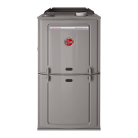
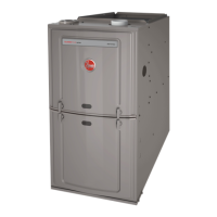
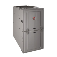
Diagram and list of furnace components for identification.
Inspect cartons for transit damage and verify unit rating plate information.
Furnace is not approved for mobile home installation; doing so can cause fire or death.
Adequate air is required for proper combustion and ventilation to prevent hazardous conditions.
Do not bypass safety switches; failure to follow can result in shock or injury.
Use approved leak detector; never use an open flame.
Install furnace 18 inches above floor in garages to prevent ignition of flammable vapors.
Select site near duct system and gas piping, considering venting needs.
Maintain clearances to combustibles and for service access.
Guidelines for connecting supply and return air plenums in upflow configuration.
Instructions for positioning and connecting ducts for horizontal furnace installations.
Ensure adequate fresh air for combustion and ventilation to prevent CO poisoning.
Requirements for air openings in confined spaces for combustion and ventilation.
Space volume requirements for unconfined spaces for combustion and ventilation.
Venting must comply with instructions, codes, and utility requirements.
Specifications for Type B-1 vent termination and sizing based on roof pitch.
Key safety information regarding fuel types, odorants, and leak detection.
Instructions for installing gas piping according to codes and best practices.
Proper natural gas and LP gas supply and manifold pressures are critical for operation.
Turn off power before making connections to prevent shock.
Cabinet must have an uninterrupted ground according to the NEC.
Steps to move the electrical junction box to the opposite side of the furnace.
Information on powering and installing an electronic air cleaner.
Humidifier output is a set of dry contacts. Logic for control detailed in manual.
Information on flue adapters and furnace filters.
Installation requirements for natural gas furnaces at altitudes above 2000 ft.
Orifice selection guidelines for LP gas furnaces at high altitudes.
Step-by-step instructions for starting the furnace operation.
Description of the furnace's operational sequence with Honeywell controls.
Diagram showing the layout of the integrated furnace control board.
Details on connecting low voltage wires to the furnace control.
Visual guide to the location and function of furnace control dipswitches.
Explanation of various dipswitch settings for system configuration.
Crucial role of the model data card for furnace operation and configuration.
Information on the dual seven-segment display for status and fault codes.
How to navigate the status modes using the pushbutton.
How the display mode changes when the pushbutton is pressed during power-up.
Details on connecting and reading supply and outdoor air temperature sensors.
Using auxiliary inputs for switches like drain pan or smoke detectors.
Wiring diagrams for communicating thermostats and systems.
Wiring diagrams for non-communicating condensers with communicating furnaces.
Wiring diagrams for legacy single-stage thermostats.
Wiring diagrams for legacy two-stage thermostats.
Wiring diagrams for non-communicating heat pumps.
Wiring diagrams for legacy single-stage heat pumps.
Wiring diagrams for legacy two-stage heat pumps.
Diagram illustrating the timing sequence for furnace operations.
Procedures for setting the furnace input rate using meter time.
Importance of proper airflow for heat exchanger function and efficiency.
Steps to measure and verify the temperature rise across the furnace.
Information found on the furnace nameplate for settings and specifications.
Function and troubleshooting for limit controls and flame roll-out switches.
How the pressure switch monitors vent system conditions.
Importance of keeping air filters clean for optimal furnace performance.
Information regarding motor lubrication and warranty.
Recommendations for annual inspection of furnace components.
List and description of normal operating codes displayed by the furnace control.
Fault codes related to model data card errors and conflicts.
Fault codes related to ignition failure and loss of flame.
Fault codes for limit control, pressure switch, and grounding issues.
Fault codes related to low pressure switch open or closed states.
Fault codes for high pressure switch open or closed states.
Fault codes related to blower cutback, no communications, or motor errors.
Fault codes for internal control faults and communication errors.
Explanation of lockout types (five-minute, one-hour, hard) and how to clear them.
Procedure for replacing the furnace control board, including data card transfer.
Flowchart to help diagnose issues with the Integrated Furnace Control.