25
DIRECT VENT
INSTALLATIONS
READ AND FOLLOW ALL
INSTRUCTIONS IN THIS SECTION.
FAILURE TO PROPERLY VENT
T
HIS FURNACE CAN CAUSE
CARBON MONOXIDE POISONING
OR AN EXPLOSION OR FIRE,
RESULTING IN PROPERTY
DAMAGE, PERSONAL INJURY
OR DEATH.
Direct vent installations require a
dedicated combustion air and venting
s
ystem. All air for combustion is taken
from the outside atmosphere and all
combustion products are discharged
to the outdoors. Therefore, no
ventilation or combustion air
openings are required.
IMPORTANT: The plastic combustion
air and venting components are of
Schedule 40 PVC. If using ABS
piping ensure that the solvent cement
is compatible for joining PVC to ABS
components or use a mechanical
connection that can withstand the
vent temperatures and are corrosion
resistant.
INSTALLATION GUIDELINES
All exhaust piping must be installed in
compliance with Part 7, “Venting of
Equipment,” of the latest edition of the
National Fuel Gas Code NPFA54/
ANSI Z223.1-, local codes or
ordinances and these instructions.
1. Vertical piping is preferred.
2. All horizontal piping must slope
upward a minimum of
1
/4 inch
per foot of run so that condensate
drains toward the furnace.
3. All horizontal runs must be
supported at least every 4 feet.
No sags or dips are permitted.
4. IMPORTANT: Do not common
vent with any other appliance. Do
not install in the same chase or
chimney with a metal or high
temperature plastic pipe from
another gas or fuel-burning
appliance unless the required
minimum clearances to
combustibles are maintained
between the PVC pipe and other
pipes.
5. For horizontal runs where water
may collect, wrap the vent pipe
with self-regulating 3 or 5 watt
heat tape. The heat tape must be
U.L. listed and installed per the
manufacturer’s instructions.
6. The minimum vent pipe length is
5 feet.
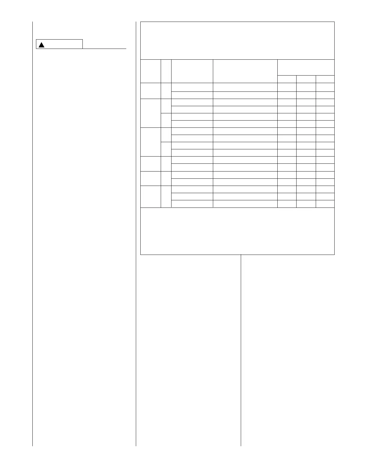
Size the exhaust and combustion air
intake pipes as specified in Table 2.
This table lists the maximum allow-
able length in feet of the exhaust and
combustion air intake pipes that may
be used for all furnace inputs as
related to the number of elbows
required and the termination (see
shaded area).
7. The maximum exposed vent
length (above the roof line) is
30ⴖ.
!
WARNING
Standard/Concentric RXGY-D02/RXGY-E03/RXGY-G02 65 60 55
4
5,000 2”
A
lternate RXGY-D02 55 50 45
S
tandard/Concentric RXGY-D02/RXGY-E03/RXGY-G02 40 35 30
2”
A
lternate RXGY-D02 30 25 20
60,000
S
tandard/Concentric RXGY-D03/RXGY-E03/RXGY-G02 120 120 120
3”
Alternate RXGY-D03 110 105 100
Standard/Concentric RXGY-D02//RXGY-E03/RXGY-G02 30 25 NR
75,000
2
”
Alternate Not Recommended NR NR NR
Standard/Concentric RXGY-D03/RXGY-E03/RXGY-G02 120 120 120
3
” Alternate RXGY-D03 100 95 85
S
tandard/Concentric RXGY-D03/RXGY-E03/RXGY-G02 110 105 95
90,000 3”
Alternate RXGY-D03 50 40 35
S
tandard/Concentric RXGY-D03/RXGY-E03/RXGY-G02 110 105 95
105,000 3”
A
lternate RXGY-D03 50 40 35
S
tandard/Concentric RXGY-D03/RXGY-E03/RXGY-G02 45 35 30
120,000 3” Alternate RXGY-D03 45 35 30
Alternate RXGY-D04 105 95 90
NOTES:
1
. N.R. - NOT RECOMMENDED.
2
. MAXIMUM OF 6 ELBOWS MAY BE USED. DO NOT COUNT ELBOWS IN ALTERNATE TERMINATION KIT.
MEDIUM OR LONG SWEEP ELBOWS MAY BE USED.
3. A 22
1
⁄2 OR 45 DEGREE ELBOW IS CONSIDERED ONE ELBOW.
4. CONCENTRIC TERMINATION NO. RXGY-E03 IS FOR THRU-THE-ROOF OR THRU-THE-WALL VENTING.
5. USE KITS RXGY-DO2 (2"), RXGY-G02 (2") OR RXGY-D03 (3") FOR STANDARD OR ALTERNATE
THRU-THE-WALL VENTING.
6. USE KITS RXGY-D04 FOR ALTERNATE VENTING OF 120,000 BTUH UNITS WITH LONG RUNS.
FURNACE
INPUT
P
IPE
S
IZE
TERMINATION
V
ENT TERMINATION
KIT RECOMMENDED
(
RXGY-D0* Kits for
Horizontal Venting Only)
1
- 2 3 - 4 5 - 6
NUMBER OF ELBOWS
4
5° or 90°
Medium / Long Radius ONLY
TABLE 2
F
OR DIRECT VENT APPLICATIONS - AIR FOR COMBUSTION
PROVIDED FROM OUTDOORS
MAXIMUM ALLOWABLE LENGTH IN FEET OF EACH EXHAUST PIPE AND INTAKE AIR PIPE
 Loading...