EasyManua.ls Logo

Rheem 90RT07EES Series - User Manual

Rheem 90RT07EES Series
60 pages
To Next Page IconTo Next Page
Loading...
92-24161-66-03
SUPERSEDES 92-24161-66-02
INSTALLATION INSTRUCTIONS
FOR HIGH EFFICIENCY CONDENSING GAS FURNACES
90RS, 90RT UPFLOW SERIES
90TS DOWNFLOW/HORIZONTAL SERIES
U.L. recognized fuel gas and CO (carbon monoxide) detectors are recommended in all
applications, and their installation should be in accordance with the manufacturer’s
recommendations and/or local laws, rules, regulations, or customs.
Upflow Models Downflow/Horizontal Models
Model Number Input (Btu) Tons Model Number Input (Btu) Tons
90RS04EES** 45,000 3 90TS04EES** 45,000 3
90RS06EES** 60,000 3 90TS06EES** 60,000 3
90RT07EES** 75,000 3 90TS07EES** 75,000 3
90RT07EFS** 75,000 4 90TS07EFS** 75,000 4
90RS09EJS** 90,000 4 90TS09EJS** 90,000 4
90RS09EGS** 90,000 5 90TS09EGS** 90,000 4.5
90RS10EGS** 105,000 4.5 90TS10EGS** 105,000 4.5
90RS12EHS** 120,000 5 90TS12EHS** 120,000 5
Question and Answer IconNeed help?

Do you have a question about the Rheem 90RT07EES Series and is the answer not in the manual?

Rheem 90RT07EES Series Specifications

General IconGeneral
BrandRheem
Model90RT07EES Series
CategoryFurnace
LanguageEnglish

Summary

INSTALLATION CHECK LIST

SAFETY INFORMATION

IMPORTANT INFORMATION ABOUT EFFICIENCY AND INDOOR AIR QUALITY

LOCATION REQUIREMENTS AND CONSIDERATIONS

CLEARANCE - ACCESSIBILITY

Information on required clearances around the furnace for service and accessibility.

SITE SELECTION

Guidelines for choosing the best location for furnace installation within the building.

DUCTING

UPFLOW UNITS

Instructions for connecting ductwork to upflow furnace models for proper airflow.

DOWNFLOW UNITS

Instructions for connecting ductwork to downflow furnace models for proper airflow.

VENTING AND COMBUSTION AIR PIPING

COMBUSTION AND VENTILATION AIR

NON-DIRECT FURNACE INSTALLATIONS

Requirements for combustion and ventilation air in non-direct vent furnace installations.

VENT PIPE INSTALLATION

DIRECT VENT INSTALLATIONS

COMBUSTION AIR FOR DIRECT VENT INSTALLATIONS

Specific requirements for combustion air supply in direct vent systems.

LOCATION REQUIREMENTS HORIZONTAL DIRECT VENTS

CONNECTING TO FURNACE

CONDENSATE DRAIN;NEUTRALIZER

CONDENSATE DRAIN FOR HORIZONTAL INSTALLATION

GAS SUPPLY AND PIPING

GAS PRESSURE

Information on proper natural gas and LP gas supply pressures for the furnace.

SETTING GAS PRESSURE

Manifold Gas Pressure Measurement.

Procedure for measuring and adjusting the manifold gas pressure for proper furnace operation.

ELECTRICAL WIRING

90+ HIGH ALTITUDE INSTRUCTIONS

START-UP PROCEDURES

TO START THE FURNACE

Step-by-step instructions for starting the furnace for the first time.

TO SHUT DOWN THE FURNACE

Instructions for safely shutting down the furnace operation.

SEQUENCE OF OPERATION

Explanation of the furnace's operational sequence during heating cycles.

ADJUSTING OR CHECKING FURNACE INPUT

SETTING INPUT RATE

Procedure for setting the furnace's input rate based on gas heating value and altitude.

AIR FLOW

TEMPERATURE RISE CHECK

Method for checking and adjusting air flow by measuring temperature rise.

SETTING BLOWER TIMINGS

GAS FURNACE (DIRECT DRIVE) INSTRUCTIONS FOR CHANGING BLOWER SPEED

Instructions for changing the blower speed settings on direct drive gas furnaces.

MAINTENANCE

ANNUAL INSPECTION

Recommendations for annual inspection and cleaning of furnace components.

TROUBLESHOOTING

Guidance for identifying and resolving furnace problems.

WIRING DIAGRAMS

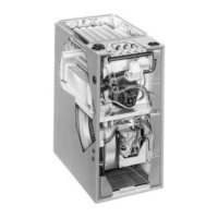
Reference to wiring diagrams for furnace control and power.

FIGURE 51 INTEGRATED FURNACE CONTROL (IFC) TROUBLESHOOTING GUIDE

Related product manuals